6. Replacement Of Parts - Page 38
WARNING:
Before commencing work open, the control panel cover (hinges down) and turn the thermostat knob to O (Off).
Allow the boiler to cool and isolate the electricity supply. Turn off the gas at the gas service cock.
IMPORTANT:
Always test for gas soundness after completing any exchange of gas carrying components and carry out
functional checks of controls.
All Models:
When removing and replacing any parts that involve draining the system, close the boiler isolation valves and
then drain the boiler using the presure gauge connection. DO NOT use the safety valve to drain the boiler.
Dv Models:
When removing and replacing any parts that involve draining the system, the manual lever on the left hand side
of the diverter valve must be moved to the 'MID' (manual override) position. Return it to its original position after the system
has been filled and vented.
Non-Dv Models with external diverter valve:
When removing and replacing any parts that involve draining the system, it
may be necessary to move a lever on the diverter valve, see manufacturers instructions for the particular valve. Return it to
its original position after the system has been filled and vented.
6.1
General Access
1.
Replacement of any component requires the removal of
the facia assembly and white front case as follows:
a.
Pull down the control cover flap to expose the facia.
Pull off the thermostat control knob. Remove the 2
screws securing the facia to the side panels and
remove the facia/control cover, carefully unclipping
the two neons as you pull the facia away.
Note:
The facia can only be completely removed from
the boiler if the pressure gauge connection is
unscrewed and the boiler drained. If fitted, disconnect
the programmer harness from the rear of the control
box.
b.
Pull the bottom of the white front case forward to
release the bottom ball studs, continue pulling until
the top studs release, then lift slightly and pull away
from the boiler.
c.
Place the case parts safely aside to avoid possible
damage.
d.
Remove the screw and unhook the bottom cover.
e.
Turn off the gas supply to the boiler at the gas
service cock (bottom L.H. corner).
f.
Turn off the water supply to the boiler at the
isolation valves.
g.
If required, remove the screw and swing out the
control box.
2.
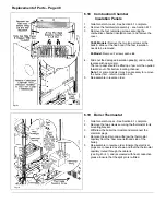
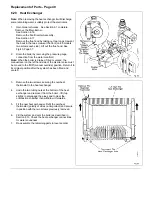
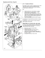
Sections 6.14 to 6.21 involve replacement of
components within the room-sealed section of the
boiler. All necessitate the removal of the combustion
chamber cover as follows:
a.
Remove the four screws securing the combustion
chamber cover and lift it off.
b.
Remove the two screws and lift off the burner heat
shield.
Re-assemble all parts in reverse order.
Summary of Contents for Ultra 2
Page 6: ...Installation Requirements Page 6 Fig 1 ...
Page 7: ...Installation Requirements Page 7 Fig 2 ...
Page 9: ...Installation Requirements Page 9 ...
Page 37: ...Routine Maintenance Page 37 ...
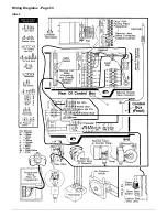
Page 51: ...7 Wiring Diagrams Page 51 ...
Page 52: ...Wiring Diagrams Page 52 Ultra 2Dv ...
Page 53: ...Wiring Diagrams Page 53 Ultra 2 ...
Page 54: ...54 Fault Finding Part No 405 0522 8 Fault Finding Guide Page 54 ...
Page 55: ...Part No 405 0522 Fault Finding 55 Fault Finding Guide Page 55 ...
Page 56: ...56 Fault Finding Part No 405 0522 Fault Finding Guide Page 56 ...
Page 57: ...Part No 405 0522 Fault Finding 57 Fault Finding Guide Page 57 ...


