Installation - Page 21
2.8
Fit the Optional Vertex Flue
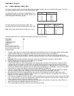
This Vertex Flue kit is only for use with the Ultra 2 Boiler and allows the flue to be run vertically from the boiler. The kit may
be used as supplied or with one, two or three flue extension kits.
It is important that the roof space is ventilated direct to the
outside with a permanent vent. The minimum effective area
of the vent is given in the table opposite.
The table opposite gives the maximum lengths of the
secondary flue which may be connected to the Vertex Flue.
Note:
The minimum length of the secondary flue is 0.5 m.
Boiler models
Minimum air vent area
30
40
50
60
80
198 cm
2
265 cm
2
330 cm
2
428 cm
2
527 cm
2
Boiler models
Max. secondary
flue length
at Min. boiler input
Max. secondary
flue length
at Max. boiler input
30
40
50
60
80
2m
5m
5.5m
8m
10m
5m
5.5m
6m
10m
12m
Carefully unpack the kit, do not discard the packaging until all the items are found.
Description
Qty
Vertex Flue
1
Vertical flue adaptor
1
Sealing plate
1
Gasket
1
M4 x 16 lg. hex. hd. screw
4
No.10 x 25 lg. pozi hd. screw
3
No.8 x 10 lg. pozi hd. screw
3
Ceiling template
1
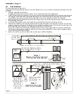
1.
Carefully unpack the kit, do not discard the packaging until all the items are found. The sealing ring and clamping plate
supplied with the boiler are not required when the Vertex Flue kit is used and should be discarded.
2.
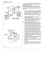
Having noted the clearances needed for installation (flue terminal & boiler), position the wall plate against the wall
(ensure it is level) and mark the position of the flue hole and a minimum of four of the mounting holes. Remove the wall
plate.
Important:
Before cutting through the ceiling ensure there are no water pipes, gas pipes or electric cables.
3.
Drill and plug the wall to accept 2½" long woodscrews (not supplied).
4.
Attach the wall plate to the wall. Ensure it is level.
A line is marked at the top of the mounting plate which indicates the centre line of the Vertex Flue. Continue this line
vertically upwards to the ceiling. This line must not be closer than 75 mm to any ceiling joist, this will ensure there is
adequate clearance for fitting and spacing from combustible material (BS5440:1:1990, sub-clause 3.3 and 4.25). Check
that the flue will terminate in accordance with the relevant recommendations given in BS5440:1. The flue must be fitted
with a terminal of a type which has been tested and found satisfactory by British Gas.
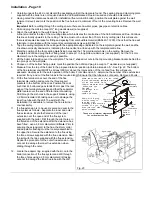
5.
Tape the ceiling template to the ceiling with the appropriate edge (indicated on the template) against the wall, and the
line drawn vertically downwards, indicating the flue centre line, lined up with the template centre line.
6.
Mark the position of the four sealing plate fixing holes and the 134 mm diameter hole on the ceiling. Remove the
template and drill and plug the four fixing holes to accept 1 in long No.8 woodscrews (not supplied). Cut the 134 mm
diameter hole in the ceiling as neatly as possible.
7.
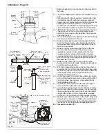
The Vertex Flue supplied is 1170 mm long. Up to three flue extensions may be used, which will give a vertex flue length
from 1170 to 4170 mm. The top of the air inlet mesh on the flue must be at least 400 mm above the roof joists, this will
ensure adequate clearance above any insulation materials.
8.
If the distance from the top raised edge of the wall mounting plate to the top of the roof joists is more than 750 mm at
least one flue extension
must
be used with the Vertex Flue.
9.
Fit the sealing plate over the flue (before any flue extensions are fitted).
Summary of Contents for Ultra 2
Page 6: ...Installation Requirements Page 6 Fig 1 ...
Page 7: ...Installation Requirements Page 7 Fig 2 ...
Page 9: ...Installation Requirements Page 9 ...
Page 37: ...Routine Maintenance Page 37 ...
Page 51: ...7 Wiring Diagrams Page 51 ...
Page 52: ...Wiring Diagrams Page 52 Ultra 2Dv ...
Page 53: ...Wiring Diagrams Page 53 Ultra 2 ...
Page 54: ...54 Fault Finding Part No 405 0522 8 Fault Finding Guide Page 54 ...
Page 55: ...Part No 405 0522 Fault Finding 55 Fault Finding Guide Page 55 ...
Page 56: ...56 Fault Finding Part No 405 0522 Fault Finding Guide Page 56 ...
Page 57: ...Part No 405 0522 Fault Finding 57 Fault Finding Guide Page 57 ...

