Replacement of Parts - Page 40
6.4
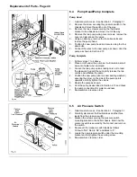
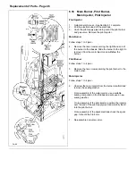
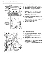
Pump Head/Pump Complete
Pump Head
1.
Gain General Access - See Section 6.1, Paragraph 1.
2.
Remove the screw securing the pressure switch to the
chassis and move the switch out of the way.
3.
Remove the two screws securing the thermostat
bracket to the chassis and move it out of the way.
4.
Remove the two pump wiring cover screws, remove the
cover and disconnect the wires.
5.
Using an allen key, remove the four allen bolts and
remove the pump head.
6.
Position the new pump head and secure using the four
allen bolts.
7.
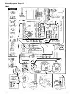
Connect the wires to the new pump as shown. Vent the
pump as shown in Section 2.13
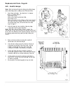
Pump Complete
1.
Perform steps 1 to 4 above.
2.
Place a cloth under the pump as it will contain a small
amount of water when removed.
3.
Loosen the two pump unions, taking care not to twist
the pipework. Support the pump,fully release the two
unions and withdraw the pump.
4.
Position the new pump (use two new sealing washers)
ensuring the arrow on the side of the pump points
upwards and fully tighten the unions.
5.
Rewire the pump as shown.
6.
Vent the pump as described in Section 2.13 and check
the pump connections for water soundness.
7.
Re-assemble in reverse order.
6.5
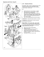
Air Pressure Switch
1.
Gain General Access - See Section 6.1, Paragraph 1.
2.
Carefully disconnect the flexible tubes and the three
leads from the pressure switch.
3.
Slacken the screw securing the pressure switch
mounting bracket to the boiler chassis. Note how the
pressure switch is secured by the bracket and remove
the switch.
4.
Reconnect the pressure switch leads as follows:
Yellow to 'NO', Red to 'NC' and Black to 'C'.
5.
Locate the new pressure switch under the mounting
bracket and fully tighten the securing screw.
6.
Re-assemble in reverse order.
Summary of Contents for Ultra 2
Page 6: ...Installation Requirements Page 6 Fig 1 ...
Page 7: ...Installation Requirements Page 7 Fig 2 ...
Page 9: ...Installation Requirements Page 9 ...
Page 37: ...Routine Maintenance Page 37 ...
Page 51: ...7 Wiring Diagrams Page 51 ...
Page 52: ...Wiring Diagrams Page 52 Ultra 2Dv ...
Page 53: ...Wiring Diagrams Page 53 Ultra 2 ...
Page 54: ...54 Fault Finding Part No 405 0522 8 Fault Finding Guide Page 54 ...
Page 55: ...Part No 405 0522 Fault Finding 55 Fault Finding Guide Page 55 ...
Page 56: ...56 Fault Finding Part No 405 0522 Fault Finding Guide Page 56 ...
Page 57: ...Part No 405 0522 Fault Finding 57 Fault Finding Guide Page 57 ...

