Installation Requirements - Page 8
1.6
Air Supply
The room in which the boiler is installed does not require a purpose provided air vent.
If the boiler is installed in a cupboard or compartment, permanent air vents are required in the cupboard or compartment,
one at high level and one at low level, either direct to the outside air or to a room. Both high level and low level air vents
must communicate with the same room or must be on the same wall to outside air. Both the high level and low level vent
must each have a free area as stated below. The free area of each vent may be halved if the ventilation is provided directly
from outside.
Models:
30: 110 cm²
40: 140 cm²
50: 180 cm²
60: 210 cm²
80: 264 cm²
If the boiler is installed in a cupboard or compartment with a door, allow at least 50 mm clearance between the front of the
boiler and the door for air movement.
1.7
Horizontal Flue System
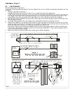
The flue/terminal assembly supplied with the boiler is 600 mm long.
A 1 m flue extension is available, if required.
Under no circumstances should the total flue length exceed 3 m. A 3 m length flue would comprise of the standard flue and
three 1m extension kits, one of which would be cut down to 400mm.
1.8
Water Connections
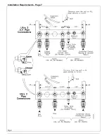
Isolation valves are supplied loose with the boiler. See Fig 2.
A short safety valve discharge pipe is provided on the boiler. It must be possible to break the joint and the remainder of the
discharge pipe (not provided) should it ever be necessary to remove the boiler from its wall plate.
Note:
The flow and return connections at the base of the boiler have been temporarily sealed with plastic plugs.
Remove
ALL
plugs before connecting the isolation valves.
Use the pressure gauge connection at the water manifold as the drain point for the boiler.
Fit one or more draining taps (BS2879) to enable the water system to be fully drained.
A factory set by pass is built into the boiler and
MUST NOT
be adjusted.
The pressure relief valve
MUST NOT
be used to drain the boiler.
1.9
Sealed System Requirements
1.
The installation must comply with the requirements of BS6798 and BS5449. Maximum water temperature is 82°C ±
3°C.
2.
A safety valve set to operate at 3 bar and a pressure gauge covering the range 0 to 6 bar are incorporated within the
boiler.
3.
A 10 litre expansion vessel to BS4841 is fitted and pre-charged to 0.5 bar. The maximum water content is shown in the
table below.
4.
Water lost from the system shall be replaced from a make-up vessel, and double check valve, mounted higher than the
top of the system or manually by a temporary hose connection, remove the temporary hose after use.See Fig 3.
Note:
Stop valves must comply with the requirements of BS1010:2.
5.
The hot water cylinder shall either be the indirect coil type or a cylinder fitted with an immersion calorifier.
6.
The automatic air vent supplied with the boiler
MUST
be fitted in a tee on a horizontal section of pipe at the highest
point in the system.
Expansion Vessel.
The expansion vessel is charged to 0.5bar. The volume of
expansion vessel varies with the overall system volume and
the cold fill pressure. The greater the cold fill pressure, the
greater the volume of the water stored in the vessel to
replace any slight water leaks. At the same time this will
reduce the maximum available system volume. The
expansion vessel volume is 10 litres. Subtract this from the
figures given in the chart opposite, to give the volume of an
additional vessel.
System Volume
(Litre)
25
50
75
100
125
150
Cold Fill Pressure (bar)
0.5
0.8
1.0
1.5
2.3
2.9
3.0
4.5
5.8
4.6
6.8
8.7
6.1
9.0
11.6
7.7
11.3
14.5
9.2
13.5
17.4
Summary of Contents for Ultra 2
Page 6: ...Installation Requirements Page 6 Fig 1 ...
Page 7: ...Installation Requirements Page 7 Fig 2 ...
Page 9: ...Installation Requirements Page 9 ...
Page 37: ...Routine Maintenance Page 37 ...
Page 51: ...7 Wiring Diagrams Page 51 ...
Page 52: ...Wiring Diagrams Page 52 Ultra 2Dv ...
Page 53: ...Wiring Diagrams Page 53 Ultra 2 ...
Page 54: ...54 Fault Finding Part No 405 0522 8 Fault Finding Guide Page 54 ...
Page 55: ...Part No 405 0522 Fault Finding 55 Fault Finding Guide Page 55 ...
Page 56: ...56 Fault Finding Part No 405 0522 Fault Finding Guide Page 56 ...
Page 57: ...Part No 405 0522 Fault Finding 57 Fault Finding Guide Page 57 ...


