Installation - Page 15
2.5
Install the Boiler and Side Flue
1.
Having noted the clearances needed for installation
(flue terminal & boiler), position the wall mounting plate
against the wall (ensure it is level) and mark the
position of the flue hole and centre, plus a minimum of
four of the mounting holes. Remove the wall mounting
plate.
Important:
Before drilling or cutting the wall ensure there
are no water pipes, gas pipes or electric cables.
2.
Drill and plug 4 holes (min.) for the wall mounting plate
to accept 2½" long woodscrews.
3.
Attach the wall mounting plate. Ensure it is level.
4.
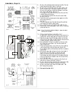
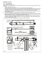
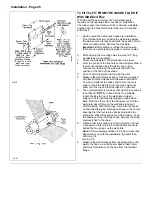
From the centre of the flue hole on the wall mounting
plate draw a level horizontal line along the wall to the
corner, continue the horizontal line along the side wall
and mark the position of the flue hole as shown. See
Fig.15.
5.
From the marked flue centre, cut a 127mm diameter
hole through the wall, if possible use a 127mm (5")
core drill.
6
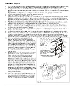
.Measure the wall thickness and cut the wall liner to the
same length. See Fig.16 Bend back the wall liner lugs
(90°).
From the inside insert the wall liner into the wall,
ensure the seam is to the top and that the tabs are
horizontal, mark, drill, plug & screw the wall liner into
position.
Make good the wall (if required).
7.
Remove the four screws and clamping plate & sealing
ring from the rear of the boiler chassis. Remove the
blanking plate from the side of the chassis & fit to the
rear flue opening.
Lift the boiler into position over the wall plate. The two
V shaped cut outs in the top mounting bracket locate
behind the two prongs on the wall plate.
Note:
If the measurement taken in paragraph 8 below
is less than 600mm carry on with the installation, if
greater than 600mm go to Section 2.5.
8.
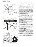
Measure the wall thickness from the edge of the outer
wall to the flue hole in the boiler chassis. Add 15mm
and mark this distance on the flue from the terminal
flange.
9.
Put wedges in the end of the flue to stop the outer flue
compressing onto the inner. Cut squarely through both
the inner and outer tubes. Remove all burrs.
10.
Choose on of the bottom boiler fixing points. Mark the
position then drill and plug to accept a 1" woodscrew
(not supplied). Insert a screw into the bottom fixing hole
& secure the boiler.
U
L
0
0
0
4
5
B
36mm
Side
Clearance
Spirit Level
Mark
for
horizontal
36mm Side
Clearance
515mm
Bottom
Clearance
Mark Off The
Flue Centre.
Use A 127mm
(5") Core Drill
To Cut Flue Hole.
Make Sure You
DO NOT Cut
Through Cables
Or Pipes
These are minimum
clearances for side flues
70mm Top
Clearance
227mm
(267mm with
wall spacer)
Mark, drill & plug
4 holes ready to
take the wall
mounting plate
securing screws,
(if a you hit a brick
joint use other
holes provided).
Fig 15
Fig 17
Summary of Contents for Ultra 2
Page 6: ...Installation Requirements Page 6 Fig 1 ...
Page 7: ...Installation Requirements Page 7 Fig 2 ...
Page 9: ...Installation Requirements Page 9 ...
Page 37: ...Routine Maintenance Page 37 ...
Page 51: ...7 Wiring Diagrams Page 51 ...
Page 52: ...Wiring Diagrams Page 52 Ultra 2Dv ...
Page 53: ...Wiring Diagrams Page 53 Ultra 2 ...
Page 54: ...54 Fault Finding Part No 405 0522 8 Fault Finding Guide Page 54 ...
Page 55: ...Part No 405 0522 Fault Finding 55 Fault Finding Guide Page 55 ...
Page 56: ...56 Fault Finding Part No 405 0522 Fault Finding Guide Page 56 ...
Page 57: ...Part No 405 0522 Fault Finding 57 Fault Finding Guide Page 57 ...


