background image

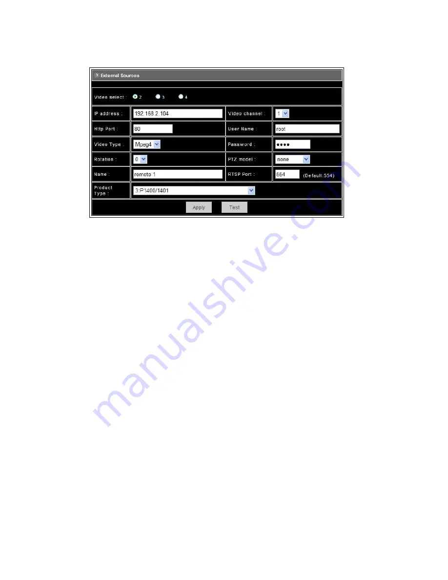
11.3 Setting External Sources 


Video Select: Select the channel this external source will be displayed. 


IP Address: Enter a valid IP address from an IP Camera or Video Server. 


Http Port: Enter the port number used for the IP address for network connection. 


Video Type: Select MJPEG or MPEG4. The type must match the external source provided. 


Rotation: Rotation degrees run from 0 to 270 degrees for a permanent digital position. 

♦ 

0: 0 degree 

♦ 

1: 90 degrees 

♦ 

2: 180 degrees 

♦ 

3: 270 degrees 


Video Channel: If the external source is a camera connected to a Video Server, select the channel 

of the Video Server. 


Username/Password: Enter the respective Username and Password if applicable. If no user has 

been set for the device, the default value should be root and pass respectively. 


RTSP Port: Enter a RTSP Port used for streaming in case the external source is a MPEG4 device. 


PTZ Model: Choose a PTZ model. 


Name: Enter a name for the device. 


Product Type: Select from MJPEG or MPEG4 Video Servers or IP Cameras. Please refer to the 

original document of the device for a better description. 


Test: Before submitting the information, click on this button to validate the video connection and the 

live video will be displayed if the settings are correct. 


Apply: Click on this button to save the changes made. 


41

Summary of Contents for P-465

Page 1: ...Pixord MPEG 4 Network Dome Camera P 465 User s Manual Date 04 09 2008 1 ...

Page 2: ...6 Fast Dome ID Address Setting Refer Chart 13 6 Installation 16 7 System Configuration 19 7 1 Fast Dome and Keyboard 19 7 2 Fast Dome Matrix and Keyboard 21 7 3 Fast Dome with PC Control 22 7 4 Fast Dome DVR and Keyboard 23 8 Software Installation 24 9 Network Configuration 25 9 1 Preparation before IP Assignment 25 9 2 Using IP Installer 25 10 Usage of Web based User Interface 28 10 1 Browse Live...

Page 3: ...ngs 35 Network Settings 35 System 36 Event 36 Others 36 11 2 Configuration of A V Setting 37 Basic A V Settings 37 Advanced A V Settings 39 Image Adjustment 40 11 3 Setting External Sources 41 11 4 PTZ Settings 42 Setting the ID for Network Dome Camera 42 Operating the Dome Camera 43 Preset Point Setting 44 Setting Preset Point 44 11 5 Setting Day Night Mode 46 11 6 Changing the Lens Speed between...

Page 4: ...61 12 9 Recalling Preset Positions 63 12 10 Setting Preset Group 63 12 11 Changing Preset Data 64 12 12 Activating Auto Pan 64 12 13 Deleting Preset Data 64 12 14 Alarm Management 65 12 15 Alarm Output 66 13 Setup Menu Tree 67 14 Fast Dome Camera Function Setup 69 14 1 Setup Menu Display 69 14 2 Language Selection 69 14 3 Display Setup 70 14 4 Dome Setting 73 14 5 Camera Setting 73 14 6 Pan Tilt S...

Page 5: ...ight Saving Time Menu 97 14 17 Display System Information 98 14 18 Camera Reset 99 15 Specification 100 15 1 Operational 100 15 2 Camera 100 15 3 Optical Lens 101 15 4 Electrical 101 15 5 Environmental 101 15 6 Mechanical 101 Appendix A 102 Quick Reference Table 102 Appendix B 103 Trouble Shooting 103 Appendix C 104 Preset ID Characters Table 104 5 ...

Page 6: ...ired the dome can be quickly spun through 180 degrees an important feature when something passes directly under the camera Up to 128 preset positions can be programmed and recalled with an accuracy of 0 25 degrees First 16 presets can be divided into 4 groups for auto touring with individual setting for speed and dwell time P465 has 6 alarm inputs expandable to 64 can drive the dome to any positio...

Page 7: ...mode Lock Mode and Release Mode Build in 1 4 CCD high resolution DSP color camera 1 Color Mono Switch IR Cut Filter In Color Out Mono Auto Switch from color to mono when light drops below 3 lux Schedule Switch from color to mono by time of setup 2 520 TV lines color 580 TV lines Mono 3 0 1 Lux Color 0 01 Lux Mono 4 On Screen Setup Menu 5 White Balance Control Auto Correction Manual 6 Back Light Co...

Page 8: ...y fixed Un suitably fixed cable may cause serious short circuit or fire 9 Correct cable connection is important Do not place any object on the connection cable and change the cable if there is damage on cable Violation may cause short circuit fire and injury 10 Make sure ground is well connected to avoid damage caused by lightning 11 Do not put any foreign objects inside the equipment and do not s...

Page 9: ...rning Do not try to repair the equipment Only a qualified technician may disassemble and repair the equipment Shut off the power before disassemble the equipment and don t put power on unless the case is completely assembled 9 ...

Page 10: ...4 Structure Element 1 Dome Cover 2 Camera Case 3 Upper Base 4 Power In Jack AC100 240V 5 Power In Jack AC24V 6 RS 485 In Out Terminal 7 Video Out Jack 8 Alarm In Out connector 10 ...

Page 11: ... Transmission speed selection 2 6 PROTOCOL SEL 1 Protocol selection 1 7 PROTOCOL SEL 2 Protocol selection 2 8 PROTOCOL SEL 3 Protocol selection 3 9 PROTOCOL SEL 4 Protocol selection 4 10 NA Using Pelco D please contact your nearest agent RS 485 In Out Terminal Resistor Setting Daisy Connection Set RS 485 In and Out terminal resistor as ON Factory Initialize Parallel Connection Set the front and la...

Page 12: ... of FULL This Mode can receive and transmit data simultaneously 5 3 Transmission Speed Setting BAUD RATE SELECTION DIP SWITCH 4 5 2400 bps ON ON 4800bps OFF ON 9600 bps ON OFF 19200 bps OFF OFF Remark LILIN Protocol use Baud Rate 9600bps 5 4 Protocol Setting PROTOCOL SELECTION DIP SWITCH 6 7 8 9 MLP 1 VERSION OFF ON ON ON 5 5 RS 485 Protocol DIP Switch for P465 Setting RS 485 PROTOCOL DIP SWITCH S...

Page 13: ...ess Setting Refer Chart Up to 64 fast dome cameras can be serial linking in one system Therefore each dome is addressing by ID switch located at the base of the fast dome When select MLP 1 camera ID setting as followings 13 ...

Page 14: ...Requirement 1 AC 100 240V Power Cable 2 AC 24V Power Cable Recommend Cable Accessory Connector Information Assemble the Cable with the Accessory Connector A Strip back the cable jacket approx 3mm and separate the individual conductors 14 ...

Page 15: ... receive signal from keyboard matrix DVR or multiplexer through twisted pair cable RS 485 Output TXDO TXDO sending out signal to next fast dome through twisted pair cable Transmission Distance Max 1 kilometer 4 Video Out BNC Jack Video Signal Output CVBS 1 0V p p 75ΩBNC Recommend Data Cable 5C2V 5 Alarm In Out Connector Each fast dome contains 6 alarm inputs and 1 alarm output Alarm Input Voltage ...

Page 16: ...6 Installation Step 2 Step 1 Separate bracket from base of bracket Step 2 Fix base of bracket on the wall Step 3 Attach camera to bracket 16 ...

Page 17: ...Step 4 Fast Dome Camera Setting Step 5 Connect Jack 17 ...

Page 18: ...Step 6 Fix bracket and outdoor fast dome camera with base 18 ...

Page 19: ...y facilitated 7 1 Fast Dome and Keyboard Single dome configuration One fast dome camera connects to one PIH 800II or PIH 931D 932T Telemetry control is sent via twisted pair between Dome and Keyboard Video signal from the dome is sent to monitor or multiplexer or quad or switcher RS 485 Connection 1st pin TXDI of RS 485 jack at back of the keyboard connects to TXDI of RS 485 jack on fast dome 2 nd...

Page 20: ...its the single data line into 4 separate data lines One keyboard can control up to 64 cameras RS 485 Connection Between PIH 804III Data Distributor and fast dome 1st output TXDI1 of PIH 804III connects to TXDI of 1 st fast dome and TXDI1 of PIH 804III to TXDI of 1 st fast dome Linking 2 nd Fast Dome TXDO of 1 st fast dome connects to TXDI of 2 nd dome and TXDO of 1 st dome to TXDI of 2 nd dome RS ...

Page 21: ...the rests are slaves Up to 8 keyboards can be sued in one system Each keyboard has a Dip Switch for ID setting Please refer to keyboard s manual for detail RS 485 Connection Between Matrix and Fast Dome TXD of receiver jack on matrix connects to TXDI of 1st fast dome and TXD of matrix to TXDI of 1 st fast dome Linking 2nd Fast Dome TXDO of 1 st dome connects to TXDI of 2 nd dome and TXDO of 1 st d...

Page 22: ...ard RS 485 IN connects to 2 nd pin TXD of matrix s keyboard jack 7 3 Fast Dome with PC Control PC telemetry remote controls fast dome with standard RS 485 data format Baud Rate 9600bps The PC control port RS 232 is converted to RS 485 format by interface User may use their own software protocol In this system up to 64 fast domes can be linked 22 ...

Page 23: ...on to the fast dome Fast dome can be controlled directly from the control panel of the DVR or from keyboard Each DVR Digital Video Recorder can manage 16 video signals and via RS 485 to daisy connection 16 sets of fast dome camera RS 485 Connection Between Fast Dome and DVR TXD of DVR RS 485 jack connects to TXDI of 1st fast dome and TXD of DVR to TXDI of the 1st fast dome Linking 2nd Fast Dome TX...

Page 24: ...igure network cameras and video servers on the LAN This utility is useful for conveniently configuring the network settings of the NDC or for finding a device once the network settings have been modified To install the IP Installer from the installation CD UI select IP installer then follow the on screen instructions Component Installer This will install all ActiveX components used by our devices ...

Page 25: ...a has a unique Ethernet address MAC address shown on the bottom of the camera as the serial number S N with 12 digits e g 000429 XXXXXX One final note although the IP Installer is able to find and configure any camera on the LAN except those that are behind a router it is a good idea to set the host PC to the same subnet In order to connect to the Web based user interface of the camera the host PC...

Page 26: ...the remote camera while saving configuration in the PC If click OK button the configuration is only saved in the PC Open the Web based UI of the Selected camera To access the Web based UI of the selected unit run the View Open Web on IP installer menu bar If the device has been configured correctly the default Web browser will open to the home page of the selected device If you find your browser i...

Page 27: ...y settings to perform a one time only installation of the ActiveX component onto your workstation as described below 1 From the Tools menu select Internet Options 2 Click the Security tab and then click Custom Level button to see your current security settings 3 Set the security level to Low and click OK 4 Type the URL or IP address of your camera into the Address field 5 A dialog box will pop up ...

Page 28: ...into full The status of the video stream 1 3 4 2 10 1 Browse Live Video Menu Language Selection The online Web based User Interface can allow the user to select 3 different languages English Traditional and Simplified Chinese Such display will not affect the original configuration for the language allowing multiple users to have different languages concurrent views In order to make the language ch...

Page 29: ...on the arrow button and select the preset point from the pull down list for quick view Manual Pan Tilt Click on the 8 directions button to move the camera to that direction Click on the rectangle button to stop the movement 180o button The viewing will turn 180 degrees Zoom Click on this button for Zooming Out Zoom Click on this button for Zooming In Iris Opens the iris and brightens the picture I...

Page 30: ...e Video Status item allows the users to see the current settings of the selected channel It also includes the function for audio control video rotation and record the video audio for the selected channel Select the Channel Click on the number tab and status for the selected channel will be displayed The settings can be setup in Configuration page On Off the Audio Select On or Off button to enable ...

Page 31: ...d other channels just repeat step 1 and 2 4 To stop recording select the channel from the tab and then click Manual Recording button again the REC message will disappear and the recording is stopped By default the recorded file will be saved in a folder named C PiXORD Recfile pppp CHx pppp The model number of the device x The number of the recorded channel The default filename will be named under ...

Page 32: ...ing Record Start recording Stop Stop recording Setting Configure the settings for Recording Camera Select the remote device Control the Video in Location Window PTZ Control To control the dome camera use the buttons on the PTZ Control panel to pan tilt and zoom the camera Zoom Click on this button to Zooming Out Zoom Click on this button to Zooming In Focus The target will become nearer Focus The ...

Page 33: ...emote File Name Input the name for the file that recorded from the remote device Cycle Recording This feature determine if the old space should be used or not for the recording Make a check mark in order to enable this function If you enable this feature old files will be deleted Sync to TimeStamp This feature enables the file to be saved according to the time When the video file is displayed the ...

Page 34: ...onnected to a Video Server select the channel of the Video Server Video Type Select MJPEG or MPEG4 The type must match the external source provided Rotation Rotate the video for view Rotation degrees run from 0 to 270 degrees 0 0 degree 1 90 degrees 2 180 degrees 3 270 degrees RTSP Port Enter a RTSP Port used for streaming in case the external source is a MPEG4 device Name Enter a name for the dev...

Page 35: ... the image of the device External Sources Set the video source for channel 2 to 4 using digital inputs IP Address PTZ Settings To control the PTZ device and set the preset points On Screen Display Set the text and location to display on the video Network Settings Functions Description General Assign an IP Address and configure the relevant network parameters to the device DDNS The DDNS Dynamic Dom...

Page 36: ...e Browse firmware location to upgrading Event Functions Description General Enable disable the event trigger and select the action when triggered Motion Area Set the area on video for motion detection Email FTP Input the Email and FTP address to receive alert message or snapshot sent by event trigger Others Functions Description Live Returns to the Live Video display Reboot Close the Web browser a...

Page 37: ... QSIF 176x120 NTSC 176x144 PAL Frame Rate The frame rate can be set between 5 to 30 FPS Encoder Format MPEG4 constant bitrates Select MPEG4 and CBR MPEG4 variable bitrates Select MPEG4 and VBR Motion JPEG Bitrate For Motion JPEG format there are 4 variable bitrates between Low and High quality For MPEG4 format there are 12 different constant bitrates to choose from 64Kbps to 4Mbps and 4 variable b...

Page 38: ...e SIF FPS 15 768Kbps recommended settings are Full D1 FPS 10 1Mbps recommended settings are Full D1 FPS 15 For higher frame rate use a variable bitrate instead However this is not recommended for Internet use Average Quality is recommended if the VBR is selected For Good Quality full resolution D1 and full frame rate 30 25 fps it is recommended that not more than 4 users connect simultaneously For...

Page 39: ...or P or I frames plus some additional data They have a much higher compression ratio than I frames I frame only mode has very little compression resulting in large file sizes I frame and P frame mode offers relatively good compression with medium file sizes Although this requires more work on the host PC to decode the video GOP Size GOP stands for Group Of Pictures It defines the number of frames ...

Page 40: ...om 100 to 100 Rotation Rotation degrees run from 0 to 270 degrees for a permanent digital position 0 0 degree 1 90 degrees 2 180 degrees 3 270 degrees Load Default Click this button to set the image adjustments back to factory default Save Click this button to save the changes made 40 ...

Page 41: ... Video Server select the channel of the Video Server Username Password Enter the respective Username and Password if applicable If no user has been set for the device the default value should be root and pass respectively RTSP Port Enter a RTSP Port used for streaming in case the external source is a MPEG4 device PTZ Model Choose a PTZ model Name Enter a name for the device Product Type Select fro...

Page 42: ...uttons is for call out the OSD Setup Menu and set up more functions Setting Day Night Mode Changing Lens Speed Switching the lens speed between default setting and manual setting Setting the ID for Network Dome Camera To select an ID number to match the ID address set by the NDC ID switch 1 Click on the arrow button beside Camera ID and select the number from the pull down list 2 Click on Apply bu...

Page 43: ...om out Click button the viewing angle becomes wider and target will become smaller on the screen 180 o Revolve The viewing angle will turn 180 o Iris Control The purpose of iris control is to adjust brightness on target It can be set as Auto Iris or Manual Iris Iris open Click button to open the iris and brighten the picture Iris close Click button to open the iris and reduce glare Auto iris Click...

Page 44: ...ist Save Remove Preset Data Click on Save button will save the current data as a preset point Click on Remove button will erase all 128 preset points Selecting Preset Group for Auto Pan Select the groups by clicking on the check boxes then click Submit button to save the changes made Activate Stop Auto Pan Activate Click the arrow button Stop Click the rectangle button Setting Preset Point Select ...

Page 45: ... the 16 preset points before Auto Scanning The first 16 preset points are separated into 4 groups Preset group must be set for the auto pan reference Group 1 includes 1st 2nd 3rd and 4th preset points Group 2 includes 5th 6th 7th and 8th preset points Group 3 includes 9th 10th 11th and 12th preset points Group 4 includes 13th 14th 15th and 16th preset points To select the groups click on the check...

Page 46: ...light drops below 3 Lux switch from color to monochrome automatically P463DW When light level is over 30 Lux IR Cut Filter switches IN automatically to produce color image When light drops below 10 Lux IR Cut Filter switches OUT automatically to produce monochrome image Under monochrome mode sensitivity is increased to 0 01 Lux and can be used with IR illuminators 11 6 Changing the Lens Speed betw...

Page 47: ...0 9 and Note The maximum display block area is 12X4 characters String length longer than 12 will feed to next line and total 4 lines are available More than 4 lines will strip off OSD Coordinate X Y To change the location of text just fill in the X and Y coordinate Display Font Grey Level Change the color of the displayed font Apply Click this button to save the changes made 47 ...

Page 48: ...e is connected This device traffic to Internet should go through Gateway if not setting this only Intranet LAN can be accessed DNS Address 1 2 and 3 The DNS server IP address used for resolving domain names to IP addresses DNS Address 2 and 3 are optional IP Setting Mode Static IP Manually assigned IP address DHCP If there is a DHCP server installed on your LAN you can select DHCP to automatically...

Page 49: ... memorized name such as http demo ddns pixord com instead of http 61 220 235 172 This service could be useful when the camera is located behind Dial up ADSL or IP sharing devices which does not have fix IP address and it s impossible to reach the camera from Internet When the camera enables the DDNS service it will register to the DDNS server with its information such as server name to access rout...

Page 50: ...g it may configure to redirect Internet HTTP port 80 request to Intranet port 8000 then in this case we must configure the Router Incoming Port to 80 and inside the camera Network settings should set HTTP port with 8000 Update Time Specify the camera updated frequency in seconds and the default is 600 10 minutes this is interval that camera will automatically send an updated packet to the DDNS ser...

Page 51: ...And the procedure is as below Configure the ADSL router with PPPoE enable LAN IP 192 168 0 254 and subnet mask 255 255 255 0 Assign the ADSL router s virtual server with service port 80 to server IP 192 168 0 200 In Network Settings General page configure the camera network configuration with IP address 192 168 0 200 subnet 255 255 255 0 DNS1 with valid DNS address such as 168 95 192 1 or 168 95 1...

Page 52: ...n Description Useful as an administrative identifier Does not affect the operation of the device Location Useful for identifying the position of the device Does not affect the operation of the device Model Displays the model number for the device Firmware Version Display firmware version information Load Default Click this button to restore the settings back to factory default Apply Click this but...

Page 53: ...e and time by clicking on the arrow button beside each field and select the value from the pull down list Click on Apply button to save the configuration Time Zone Click on the arrow button and select the appropriate time zone from the pull down list NTP Server 1 2 and 3 Assign the NTP servers to use for time synchronization A list of NTP servers can be found at http www eecis udel edu mills ntp c...

Page 54: ...General group can be configured to have limited permission to operate the device Delete User To remove a user select the user from the list and then click on Delete User button Note Totally 10 users can be added The first added user must have administrative right Administrator group and must be the last one to be removed The username and password cannot contain the characters And the length must b...

Page 55: ...11 10 Firmware Upgrade To upgrade firmware first browse the folder where you have placed the newest firmware After finding the path then click on Update to upgrade the device 55 ...

Page 56: ...P Image Mail Image or on all of them to determine what action should be taken when the event is triggered FTP Image Send the image to the configured FTP site when event is triggered Click on the link to set the FTP server Mail Image Send the image to the configured mail address when event is triggered Click on the link to set the Email addresses Alert Message Status They are auto detected to displ...

Page 57: ...tion Use mouse to drag out a detection area on the video Left click the area and drag the corner to change the size Right click the area and select Property Check Enable click OK and click Apply Note Green blocks indicate this area is enabled for detection Red blocks indicate this area is not enabled for detection 57 ...

Page 58: ... mail server name or IP address Authorization Disable or enable the security for mail authorization Account ID and Password Enter the user name and password for the mail sender FTP Setting The FTP Image checkbox Configuration Event General Action must be enabled when use this function Host Name Enter the IP address of the FTP server User Name and Password Enter the user name and password for the F...

Page 59: ...until an operator cancels it 12 2 Manual Operation Pan Tilt Control To control the pan and tilt movement of the dome simply use the joystick on the keyboard to pan the camera left push the joystick to the left to tilt down pull the joystick down towards you To move the dome faster push the joystick further in that direction the joystick is proportional to the speed of the dome a small movement wil...

Page 60: ...larged on the screen Zooming will stop when the key is released To Zoom Out Push key The viewing angle becomes wider and target will become smaller on the screen Zooming will stop when the key is released 12 5 Focus Control The focus function on Fast Dome can be set as Auto Focus or Manual Focus Manual focus far key Push key The target will become farther Focusing will stop when the key is release...

Page 61: ...er the camera Two ways to operate 180 instant flip Push key on keyboard to flip the camera 180 horizontally Push joystick down to bring the camera down to the end release the joystick and quickly push joystick down twice to flip the camera 180 horizontally 12 8 Preset Position Setting Each dome can have 128 individual preset positions Each preset stores the exact position of the camera and automat...

Page 62: ...ls to that preset position can be adjusted between 1 to 255 per second factory default is 255 sec To set speed as 10 sec Push key followed by key two beeps will be heard confirming that speed is set Note Push key again to confirm speed entered Setting Preset Dwell Time The dwell time means the time user wants to view on certain preset position under Auto Pan The Preset Dwell Time can be set betwee...

Page 63: ...all the 1 st Preset Position Push followed by key The dome will move to that position in speed of 360 sec EX To recall 1st preset position keys To recall 128 th preset position keys 12 10 Setting Preset Group The purpose of setting preset group allows the management of the 16 preset positions before Auto Scanning The first 16 preset positions of each dome are separated into 4 groups Preset group m...

Page 64: ... dome will auto touring the preset groups entered To activate Auto Pan Push key confirming the activation of auto pan Auto Pan Led will be lit To stop Auto Pan Push key again confirming the stop of auto pan Auto Pan Led will be off Note If Auto Pan is activated no other commands can be sent to that dome but other dome can still be selected and operate manually To select call out another dome while...

Page 65: ... between alarmed points then reverts to prior status such as auto pan Lock Mode When an alarm is triggered the dome will go to the relevant position at 360 sec and the keyboard will audio alert user until it is canceled manually To manually cancel the alarm trigger push key If more than one alarm is triggered the fast dome will lock on the last alarm triggered position Release Mode 1 Under Auto Pa...

Page 66: ... triggered NC contact to Common will be open and NO contact to common will be close Alarm output will be back to the condition before alarm 10 seconds after the last alarm is triggered When alarm response mode is set to RELEASE Mode When the alarm is triggered NC contact to Common will be open and NO contact to common will be close Alarm output will be back to the condition before alarm 60 seconds...

Page 67: ...13 Setup Menu Tree 67 ...

Page 68: ...68 ...

Page 69: ...etup Menu Display Press key on the keyboard to recall setup menu Press key to exit setup menu or push joystick down to select EXIT and then press key to exit setup menu 14 2 Language Selection Press key into setup menu Push joystick down to select LANGUAGE and then push joystick left or right to make selection Press key to exit setup menu or push joystick down to select EXIT and then press key to ...

Page 70: ...n displayed on the monitor screen until elapsed time stops when Preset ID is recalled 3 Zoom Ratio Setting Push joystick down to select ZOOM RATIO and then push joystick left or right to make selection OFF No Zoom Ratio on the monitor screen 1 255 sec Display elapsed time Zoom Ratio will have been displayed on the monitor screen until elapsed time stops when Zoom Ratio is operated 4 Alarm Message ...

Page 71: ...set Time Adjustment Push joystick down to select TIME and then press key to setup time Push joystick left or right to adjust time and then press key to next item of time Date Adjustment Push joystick down to select DATE and then press key to setup date Push joystick left or right to adjust date and then press key to next item of date Date Format Setting Push joystick down to select DATE FORMAT and...

Page 72: ...lt Angle Setting Push joystick down to select PAN TILT ANGLE and then push joystick left or right to select pan tilt setup OFF No Pan Tilt Angle on the monitor screen ON Pan Tilt Angle on the monitor screen 72 ...

Page 73: ...dome setting menu 14 5 Camera Setting 1 Display the Camera Setting Menu After getting in dome setting menu push joystick down to select CAMERA and then press key into camera setting menu 1 Auto Focus Setting Push joystick down to select AUTO FOCUS and then push joystick left or right to select auto focus mode 73 ...

Page 74: ...ge is X18 X35 4 Zoom Speed Setting Push joystick down to select ZOOM SPEED and then push joystick left or right to adjust zoom speed setting Zoom speed range is 00 07 5 Focus Speed Setting Push joystick down to select FOCUS SPEED and then push joystick left or right to adjust focus speed setting 6 Auto Iris Setting Push joystick down to select AUTO IRIS LEVEL and then push joystick left or right t...

Page 75: ...stick left or right to made selection 2 Backlight Compensation Setting Push joystick down to select BACKLIGHT and then push left or right to select ON or OFF Note When ON is selected the brightness gain is automatically controlled for backlight compensation in response to the light intensity detection window 3 Flicker Less Push joystick down to select FLICKER LESS and then push joystick left or ri...

Page 76: ...ure Confirm color temperature and then press key to recode datum in the memory 5 IR Cut Filter Setting Push joystick down to select IR CUT REMOVE and then push joystick left or right to select mode Auto When light level is over 30 lux IR Cut Filter switches IN automatically to produce color image When light drops below 10 lux IR Cut Filter switches OUT automatically to produce monochrome image Und...

Page 77: ...press key into time setting Push joystick left or right to select time of DAY NIGHT Then press key again to next item Push joystick down to delete NIGHT DAY and then press key into time setting Push joystick left or right to select time of NIGHT DAY The press key again to next item IN IR Cut Filter is ON and always produce constant color image OUT IR Cut Filter is OFF and always produce constant m...

Page 78: ... step is 3 5 phase adjustment is 0 350 7 Auto Gain Control Setting Push joystick down to select AGC LIMIT and then push joystick left or right to make selection Auto Gain Control range is 0db 3db 3 Image Setting After getting in advanced setting menu push joystick down to select IMAGE and then press key into image setting menu 1 Gamma Setting Push joystick down select GAMMA and then push joystick ...

Page 79: ...etting Push joystick down to select RESOLUTION and then push joystick left or right to make selection HIGH or NORMAL High 520 TV lines Normal 480 TV lines 14 6 Pan Tilt Setting Menu 1 Display the Pan Tilt Setting Menu After getting in the dome setting menu push joystick down to select PAN TILT and then press key into pan tilt setting menu 2 Home Position Setting Push joystick down to select HOME P...

Page 80: ...Home Perform return home position mode Auto Perform auto scan mode SEQ Perform preset group mode TOUR 1 Perform tour 1 list mode TOUR 2 Perform tour 2 list mode PATROL Perform memory patrol mode Note When keyboard control isn t used and Return Time is also over Return Mode function will be started 5 Auto Mode Setting Push joystick down to select AUTO MODE and then push joystick left or right to se...

Page 81: ...ting menu Push joystick left right up or down to select start position and then press to adjust zoom focus iris then press key to confirm Push joystick left or right to select end position and then press key to confirm 2 Dwell Time Setting Push joystick down to select DWELL TIME and then push joystick left or right to select dwell time 1 255 sec 3 Scan Speed Setting Push joystick down to select SC...

Page 82: ...ARN and then press key into setting menu Control joystick or press control key of lens to start patrol learn mode Count down time from 100 1 Press key to end patrol learn mode Note Patrol mode can record all control action of keyboard and when Auto Pan Function is select camera will perform patrol mode before setting 2 Clear Memory of Patrol Push joystick down to select CLEAR and then press key to...

Page 83: ...NUMBER Push joystick down to select PRESET NUMBER then push joystick left or right to select preset number 1 128 Select number by PRESET MAP 1 Push joystick down to select PRESET MAP and then press key into preset map 2 Push joystick left right up or down to select preset number and then press key into preset setting menu 3 If need to select preset numbers 33 64 push joystick down to 33 64 then pr...

Page 84: ...ct character and press key to confirm The character selected will be showed in edit area If you need space push joystick down to select SPACE and press key to confirm Press or to switch to next character list Repeat all steps to complete preset ID 2 Copy preset ID to Another Preset Push joystick down to select EDIT AREA and push joystick left or right to select first copy of characters Push joysti...

Page 85: ... Preset ID Push joystick down to CANCEL then press key to cancel preset ID 5 Preset ID Position Setting Push joystick down to POSI and press key to get in Push joystick to move preset ID to needful position of frame then push key to confirm 6 Return Preset Setting Push joystick down to OK and then press key to back to preset menu 5 Scene File of Preset Setting Push joystick down to select SCENE FI...

Page 86: ... press key to confirm ABOVE NUM Only cancel parameter of allotted preset ALL Cancel parameters of all presets 1 128 14 8 Tour Function Setting Menu 1 Display the Tour Setting Menu After getting in dome setting menu push joystick down to select TOURS then press key into tours setting menu 2 Tour Number Selection Push joystick down to select NUMBER then push joystick left or right to select Tour 1 o...

Page 87: ...ick left or right to select dwell time of tour 1 255 sec Note When Self Return Mode or Auto Mode is Tour dwell time of Auto Pan will be dwell time setting of tour 6 Speed Setting Push joystick down to select SPEED then push joystick left or right to select preset speed 1 255 deg sec Note When Self Return Mode or Auto Mode is Tour speed of Auto Pan will be speed setting of tour 87 ...

Page 88: ...tick down to select EDIT ZONE then press key into Edit Zone mode Also middle of monitor will display privacy zone mask area Push joystick left or right to adjust privacy mask position Adjust optical zoom lens and auto focus then press key to confirm and get into privacy zone mask area for editing Press key then push joystick left right up or down to extend privacy zone mask area Press key then pus...

Page 89: ...ing in dome setting menu push joystick down to select ALARMS then press key into alarms setting 2 Input of Alarm Setting Push joystick down to select IN 1 to IN 6 then push joystick left or right to select ON or OFF 3 Input of Alarm Mode Setting Push joystick down to select IN MODE then push joystick left or right to select NO or NC NO mode Contact of input alarm is normally open If contact is sho...

Page 90: ...select event return time 1 99 min 14 11 Password Function Menu 1 Display the Password Setting Menu After getting in dome setting menu push joystick down to select PASSWORD then press key into password function menu 2 Password Setting Push joystick down to select ENABLE PASSWORD then push joystick left or right to select ON or OFF 3 Edit Password Setting Push joystick down to select EDIT PASSWORD t...

Page 91: ...sword completed please get in EDIT PASSWORD again to edit If password function is ON previous passwords have to enter on the setting menu first and then do modifying password 5 Input Password After password function is ON press key to display frame of input password on the screen When protocol is MLP 1 push joystick up or down to select number 0 9 then press key to confirm Select numbers will beco...

Page 92: ... press key into factory initial setting 2 Factory Initial for ALL Push joystick down to select RESTORE then push joystick left or right to select ALL Press key to confirm and Are you sure continue will be displayed on the screen Press key again then do factory initialization for all Note PLEASE WAITING FACTORY INITIALIZATION will show on the screen after confirmation 92 ...

Page 93: ...en push joystick left or right to select CAMERA Press key to confirm and Are you sure continue will display on the screen Press key again then do factory initialization for camera Note Check again If not press key to confirm within 3 sec this command will be canceled 93 ...

Page 94: ...nto schedule setting menu push joystick down to select ALARM IN then press key into alarm input schedule setting menu 2 Start Alarm Input Schedule Setting Push joystick down to select STARTUP then push joystick left or right to select ON or OFF OFF Alarm input schedule function is OFF alarm input trigger will not be limited by schedule time ON Alarm input schedule function is ON alarm input trigge...

Page 95: ...hen push joystick left or right to select end time and press key for next item Note When alarm input schedule function is ON and end time is also up alarm input trigger will be stopped 14 15 Start Auto Options Menu 1 Display the startup Auto Options Setting Menu After getting into schedule setting menu push joystick down to select STARTUP AUTO OPTIONS then press key into startup auto options setti...

Page 96: ...n auto setting mode will start 2 While schedule is performing if power failed and restored schedule will not continue to perform until next schedule time start 3 While schedule is STOP Mode if camera is set Self Return Mode and Self Return Time is up camera will perform Self Return Mode till next schedule time start Example 1 12 00 perform SEQ mode 2 13 00 STOP If Self Return Mode is home Home Pos...

Page 97: ...Time Function Setting Push joystick down to select STARTUP then push joystick left or right to select ON or OFF 3 Start Time Setting Push joystick down to select START and press key into setting mode then push joystick left or right to select start time Then press key for next item 4 End Time Setting Push joystick down to select END and press key into setting mode then push joystick left or right ...

Page 98: ...stem information Push joystick down to select BACK and then press key to go back or push joystick down to select EXIT then press key to exit setup menu Display system information 1 Fast dome model number 2 Camera Pan Tilt Receiver version 3 Font of OSD version 4 Protocol rate and format 5 Fast dome ID number 6 Protocol version LILIN717 MLP1 98 ...

Page 99: ...to perform initial setting of camera Press key into setup menu Push joystick down to select CAMERA RESET and then press key to restart camera Press key to exit setup menu or joystick down to select EXIT and then press key to exit setup menu 99 ...

Page 100: ...esponding with first 16 presets 1 64 ID Setting Protocol is MLP1 15 2 Camera Image Device 1 4 inch interline transfer CCD Horizontal Vertical Pixel 768 x 494 NTSC 752 x 582 PAL Scanning System 2 1 Interlace Horizontal Resolution 580 TV lines Monochrome 520 TV lines Color Minimum Illumination 0 01 Lux at F1 6 Monochrome 0 1 Lux at F1 6 Color S N Ratio 50dB AGC OFF Synchronization Internal line Lock...

Page 101: ...trical Power Supply L type 24VAC or F type 100VAC 240VAC Option Power Consumption 22 W Heater ON Control Interface RS 485 1 Input 1 Output RS 485 Voltage 5 6V Alarm Input 6 Inputs Pull up Alarm Input Voltage 5 6V Alarm Output 1 Output NC or NO mode Alarm Output Voltage 1 A 24 VDC Alarm Response Mode Lock or Release Mode 15 5 Environmental Operation Temperature 10 C 50 C Operation Humidity 0 90 15 ...

Page 102: ...Appendix A Quick Reference Table 102 ...

Page 103: ...n on monitor 3 No Telemetry Check camera ID switch setting Check RS 485 cable IN OUT connection on camera Check RS 485 cable IN OUT connection on keyboard Check if the fast dome is under Auto Pan Mode please deactivate Auto Pan Check if alarm is triggered cancel triggered alarm 4 Poor Focusing Dusts on dome cover or housing cover Clean the cover with cotton cloth 103 ...

Page 104: ...Appendix C Preset ID Characters Table 104 ...

Reviews: