INSTALLATION
Sept-2018
28
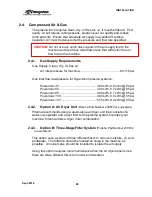
2.4. Compressed Air & Gas
The plasma torch requires clean, dry, oil free air, i.e. it must be filtered. Poor
quality air will reduce cutting speeds, produce poor cut quality and reduce
torch parts life. Ensure that adequate air supply is available for stable
operation. Air must be delivered at the pressure and flow rate specified.
CAUTION:
Do not use any quick disconnects in the air supply line to the
machine as these have small flow areas that will restrict the air
flow rate to the machine.
2.4.1.
Gas Supply Requirements
Gas Supply: Clean, dry, oil-free air
Air inlet pressure for machine: ................................................80-110 psi
Gas inlet flow rate/pressure for Hypertherm plasma systems:
Powermax 45
............................................. 360 scfh; 6.0 scfm @ 80 psi
Powermax 65 .............................................
400 scfh, 6.7 scfm @ 85 psi
Powermax 85 .............................................
400 scfh, 6.7 scfm @ 85 psi
Powermax 105 ...........................................
480 scfh, 8.0 scfm @ 85 psi
Powermax 125 ...........................................
550 scfh, 9.2 scfm @ 85 psi
2.4.2.
Option A: Air Dryer Unit
(Piranha Part Number 230579 or equivalent)
Piranha recommends using a stand-alone air dryer unit that consists of a
water-oil-separator and a post filter for the plasma system to protect your
machine. Piranha offers a dryer / filter combination.
2.4.3.
Option B: Three-Stage Filter System
(Piranha Part Number 230634
or equivalent)
This option uses a series of three different filters to remove moisture, oil, and
particulate. The filtration should be located as close to the machine as
possible. An outlet valve should be installed to isolate the air supply.
Using this option requires more maintenance than the air dryer option since
there are three different filters to monitor and maintain.
Summary of Contents for CNC Plasma Cutting Table
Page 2: ......
Page 4: ...TABLE OF CONTENTS Sept 2018 4...
Page 22: ...SAFETY Sept 2018 22...
Page 24: ...INSTALLATION Sept 2018 24...
Page 88: ...PROGRAMMING Sept 2018 88...
Page 117: ...PIPE CUTTING ATTACHMENT Sept 2018 117 Pipe Supports Pipe Cutter Base...
Page 124: ...PIPE CUTTING ATTACHMENT Sept 2018 124...
Page 128: ...PIPE CUTTING ATTACHMENT Sept 2018 128 j Then press F2 SYSTEM to see the following...
Page 136: ...PIPE CUTTING ATTACHMENT Sept 2018 136...
Page 140: ...WATER MIST CHILLER Sept 2018 140...
Page 144: ...APPENDIX A FastCAM SETUP Sept 2018 144 4 Choose the functions you need and Enter...
Page 154: ...APPENDIX A FastCAM SETUP Sept 2018 154...
Page 159: ...APPENDIX A FastCAM SETUP Sept 2018 159...
Page 164: ...APPENDIX A FastCAM SETUP Sept 2018 164...
Page 170: ...APPENDIX B Parametric Shape Library Sept 2018 170 9 Fla X 10 Lad 11 Rec 12 Rec8...
Page 172: ...APPENDIX B Parametric Shape Library Sept 2018 172 19 Rec 20 Rec c 21 Circle4 22 Rec...
Page 174: ...APPENDIX B Parametric Shape Library Sept 2018 174...

