SAFETY
Sept-2018
17
Sparks
Sparks form as the plasma arc torch vaporizes metal. These sparks are tiny
droplets of extremely hot molten metal and are a possible fire hazard. The volume
of sparks formed and the area over which they are scattered depend on several
variables. These variables include the type and thickness of the material being cut,
the cutting current, and the feed rate. Where practical, keep all combustible material
at least 35 ft. (10.7 m) away from the plasma arc work area. Where this is not
practical, protect all combustible materials with close fitting, flame proof covers or
shields. Protect wooden or other combustible floors by covering them with sand or
installing fire-resistant shields. Shield any wall openings, floor openings, cracks,
ducts, or conveyors within 35 ft. (10.7 m) of the torch to prevent sparks from passing
into adjacent areas.
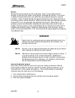
WARNING
Sparks from the cutting process may ignite flammable items in the
machine bed which may then be drawn into the extraction unit,
possibly causing a fire.
NOTE:
Be sure to use an approved facemask and approved eye protection
when cleaning or servicing the dust collector.
NOTE:
Plasma arc cutting systems can produce large volumes of fumes. If
you exhaust fumes to the outside atmosphere, additional air
pollution control devices may be in order to conform to local, state,
and federal government ordinances. Air pollution control devices
are the responsibility of each individual user.
Internal Ventilation System
Due to the noxious and toxic nature of many torch cutting by-products, Piranha
recommends venting the machine's internal ventilation system (referred to as the
"dust collector") to the outside atmosphere. This recommendation is especially
important when the shop has one of the following:
1. Low ceilings and/or confined area
2. Large amount of welding and/or torch cutting near the plasma system
3. Poor cross plant ventilation
Summary of Contents for CNC Plasma Cutting Table
Page 2: ......
Page 4: ...TABLE OF CONTENTS Sept 2018 4...
Page 22: ...SAFETY Sept 2018 22...
Page 24: ...INSTALLATION Sept 2018 24...
Page 88: ...PROGRAMMING Sept 2018 88...
Page 117: ...PIPE CUTTING ATTACHMENT Sept 2018 117 Pipe Supports Pipe Cutter Base...
Page 124: ...PIPE CUTTING ATTACHMENT Sept 2018 124...
Page 128: ...PIPE CUTTING ATTACHMENT Sept 2018 128 j Then press F2 SYSTEM to see the following...
Page 136: ...PIPE CUTTING ATTACHMENT Sept 2018 136...
Page 140: ...WATER MIST CHILLER Sept 2018 140...
Page 144: ...APPENDIX A FastCAM SETUP Sept 2018 144 4 Choose the functions you need and Enter...
Page 154: ...APPENDIX A FastCAM SETUP Sept 2018 154...
Page 159: ...APPENDIX A FastCAM SETUP Sept 2018 159...
Page 164: ...APPENDIX A FastCAM SETUP Sept 2018 164...
Page 170: ...APPENDIX B Parametric Shape Library Sept 2018 170 9 Fla X 10 Lad 11 Rec 12 Rec8...
Page 172: ...APPENDIX B Parametric Shape Library Sept 2018 172 19 Rec 20 Rec c 21 Circle4 22 Rec...
Page 174: ...APPENDIX B Parametric Shape Library Sept 2018 174...


