APPENDIX A
– FastCAM SETUP
Sept-2018
147
5.
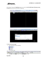
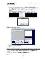
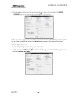
When you click
and close the sub-
page (push ESC if necessary), you will see a 4” square
with a 1” round hole right in the middle;
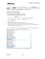
6.
Push
Files
on the top left of the tool bar, choose
Save
to save the part in a
*.CAM
file; or
DXF Save
to
save the part in a
*.DXF
file. Then follow the instruction, name the part drawing and save it to certain
path on your computer or USB.
Summary of Contents for CNC Plasma Cutting Table
Page 2: ......
Page 4: ...TABLE OF CONTENTS Sept 2018 4...
Page 22: ...SAFETY Sept 2018 22...
Page 24: ...INSTALLATION Sept 2018 24...
Page 88: ...PROGRAMMING Sept 2018 88...
Page 117: ...PIPE CUTTING ATTACHMENT Sept 2018 117 Pipe Supports Pipe Cutter Base...
Page 124: ...PIPE CUTTING ATTACHMENT Sept 2018 124...
Page 128: ...PIPE CUTTING ATTACHMENT Sept 2018 128 j Then press F2 SYSTEM to see the following...
Page 136: ...PIPE CUTTING ATTACHMENT Sept 2018 136...
Page 140: ...WATER MIST CHILLER Sept 2018 140...
Page 144: ...APPENDIX A FastCAM SETUP Sept 2018 144 4 Choose the functions you need and Enter...
Page 154: ...APPENDIX A FastCAM SETUP Sept 2018 154...
Page 159: ...APPENDIX A FastCAM SETUP Sept 2018 159...
Page 164: ...APPENDIX A FastCAM SETUP Sept 2018 164...
Page 170: ...APPENDIX B Parametric Shape Library Sept 2018 170 9 Fla X 10 Lad 11 Rec 12 Rec8...
Page 172: ...APPENDIX B Parametric Shape Library Sept 2018 172 19 Rec 20 Rec c 21 Circle4 22 Rec...
Page 174: ...APPENDIX B Parametric Shape Library Sept 2018 174...


