background image

PARTS MANUAL - SPECIFY MODEL NUMBER AND  

SERIAL NUMBER WHEN ORDERING PARTS 

Sept-2018 


114 


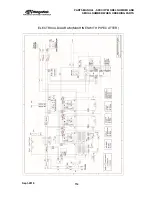
ELECTRICAL DIAGRAM (MACHINES WITH PIPE CUTTER) 


Summary of Contents for CNC Plasma Cutting Table

Page 1: ...CNC Plasma Cutting System Operating Manual Revised September 14 2018 www piranhafab com 800 338 5471...

Page 2: ......

Page 3: ...INSTALLATION 25 OPERATIONS 47 PROGRAMMING 85 MAINTENANCE 89 PARTS MANUAL 105 PIPE CUTTING ATTACHMENT OPTIONAL EQUIPMENT 115 WATER MIST CHILLER OPTIONAL EQUIPMENT 137 APPENDIX A FASTCAM SETUP 141 APPEN...

Page 4: ...TABLE OF CONTENTS Sept 2018 4...

Page 5: ...rogrammers machine operators and maintenance personnel be trained adequately in the use and care of the equipment These employees should receive the proper instruction in order to have a complete unde...

Page 6: ...3 Wear proper clothing Do not wear watches rings jewelry or loose fitting clothes 4 Read and review the manual carefully 5 Be familiar with the operation of the machine 6 Practice preventative mainte...

Page 7: ...d by applicable federal local industry and plant safety program standards 5 Wear proper clothing Do not wear watches rings jewelry or loose fitting clothes 6 Avoid all moving parts of the machine or w...

Page 8: ...cing the torch power supply or service connections to the plasma arc system or any part of the machine bed Wear adequate personal equipment overalls gloves safety boots etc when operating the machine...

Page 9: ...duce reflection Protective screens or curtains may be installed to avoid unnecessary ultra violet transmission INPUT CONNECTIONS 1 A wall mounted line isolating switch fused as required by local elect...

Page 10: ...onnect all positive output ground leads to the material grid of the work table 2 Connect the material grid of the work table to a good earth ground BURN PREVENTION High intensity ultraviolet and infra...

Page 11: ...esh air such as a respirator or air supplied helmet Metals coated with materials that emit toxic fumes must not be cut unless 1 The coating is removed prior to cutting 2 The area is adequately ventila...

Page 12: ...Do not resume cutting until you locate and control the source of the vapors Various cleaning solvents and vapor degreasers contain chemicals that decompose rapidly when exposed to ultraviolet radiati...

Page 13: ...rnal ventilation system is functioning normally there should be adequate control of metal dust during torch cutting For proper ventilation at least 90 of the worktable should be covered by the workpie...

Page 14: ...ical contact such as welding arcs with cylinders Never expose cylinders to excessive heat sparks slag or open flames which may cause rupture Never use hammers wrenches or other tools to open stuck val...

Page 15: ...ds for more information on hoses SAFETY DEVICES Plasma arc units are provided with certain safety interlocks designed to prevent equipment damage and or personal injury Never short out or in any way a...

Page 16: ...tem is off IMPORTANT Read this manual thoroughly before operating the machine Read the Torch Height Control Manual before operating the machine Read the CNC Control Operator Manual before operating th...

Page 17: ...acent areas WARNING Sparks from the cutting process may ignite flammable items in the machine bed which may then be drawn into the extraction unit possibly causing a fire NOTE Be sure to use an approv...

Page 18: ...to radiant energy Shield personnel at nearby workstations from accidental exposure to radiant energy by the use of non reflective fireproof enclosures open at the top and at floor level to allow air...

Page 19: ...arc plasma torch nozzle design gas velocity material type and plate thickness Piranha recommends that each user check the sound levels in his own shop under normal operating conditions Based on those...

Page 20: ...pany to make sure safety information covering the equipment being used and its particular application is available to personnel operating and maintaining the equipment and is read by them SAFETY STAND...

Page 21: ...partment please give the model number serial number and purchase date of the equipment Megafab P O Box 1206 Rockford Illinois 61105 USA Telephone 815 490 0472 Fax 815 964 3175 The preceding safety ins...

Page 22: ...SAFETY Sept 2018 22...

Page 23: ...vo Motors Y Axis Servo Motor Torch Height Control Stepper Motor Mechanical Drive System X Axis Rack Pinion 2 Y Axis Rack Pinion Z Axis Ball Screw Available Plasma Torches Hypertherm Powermax 45XP Hype...

Page 24: ...INSTALLATION Sept 2018 24...

Page 25: ...de you from unpacking to setting up your table for your first cut If something needs better explanation please contact us 2 PRIOR TO RECEIVING 2 1 Space Location The following drawing shows the requir...

Page 26: ...ER WEIGHT 4 X4 88 116 1 500 lbs 800 lbs 4 X8 144 116 2 000 lbs 800 lbs 5 X10 164 126 2 500 lbs 800 lbs C408 and C510 Machines with pipe cutters require shipment as an oversize over width load It is no...

Page 27: ...unted fused quick disconnect electrical box in a convenient location near the machine for the plasma system 2 3 3 Earth Ground The machine foundation area must have an adequate ground rod to reduce el...

Page 28: ...360 scfh 6 0 scfm 80 psi Powermax 65 400 scfh 6 7 scfm 85 psi Powermax 85 400 scfh 6 7 scfm 85 psi Powermax 105 480 scfh 8 0 scfm 85 psi Powermax 125 550 scfh 9 2 scfm 85 psi 2 4 2 Option A Air Dryer...

Page 29: ...on plasma systems greater than 85 amps Powermax105 and Powermax125 NOTE When using the water table water and slag must be disposed of in accordance with state and local codes 2 6 Required Equipment To...

Page 30: ...t any maneuver is undertaken safely Damage caused to the machine through incorrect or careless maneuvers is not covered under the machine warranty Megafab is not responsible for personal injury to any...

Page 31: ...Longer lifting straps may be required if the crane does not have hoist chains attached 3 Slide one of the lifting strap under the machine base close to the gantry side as shown on the picture below 4...

Page 32: ...hine above the truck bed and confirm that load is not tipping in either direction by doing a complete walkaround 10 Reposition straps and crane as necessary to keep load stable and balanced 11 Once th...

Page 33: ...ck bed 2 Drive the forklift to the side of the truck at the lifting points shown in the picture below NOTE The forklift must not lift the machine from the cable carrier side instead lifting must be do...

Page 34: ...d up as close to the center of gravity as possible 7 Once the load is balanced and stable lift the machine clear of the vehicle CAUTION Before moving the machine into position it is essential to plan...

Page 35: ...to floor level and place it firmly on the ground at the designated area of operation NOTE Ensure machinery skates are placed in all four corners of the machine base if they are used 3 2 Unpacking 1 R...

Page 36: ...rs The cover for the cable carrier side has an extra bracket attached to it 2 Take the cable carrier side cover and place it over the motor Ensure that cables are routed under the bracket as shown in...

Page 37: ...2 Determine the side that is higher of the two based on the water bubble 3 Loosen the lock nut on the higher side of leveling pad and drop the height of the pad by rotating the threaded bolt with wre...

Page 38: ...Move on to the remaining x axis surface parallel to the first x axis surface and place a level on it 9 Adjust the pad by loosening the lock nut and rotating the threaded bolt with a wrench until the...

Page 39: ...t available remove the 90 degree fitting and replace it with the supplied adapter for 1 4 NPT 2 Set the pressure on air regulator to above 4 5 bar Note the pressure must be above 4 bar always or else...

Page 40: ...ines to the terminals on the main disconnect 3 Run the ground wire to the ground bar 4 Run 10 gauge wire green or green yellow from the ground rod to the ground bar Connect it at both ends 5 Connect t...

Page 41: ...wer supply 2 Insert the plug from the grey cable into the connection at the top right on the rear of the Powermax power supply 3 Insert a compressed air line into the rear of the Powermax power supply...

Page 42: ...8351 5 8 Diameter Tube Clamp Qty 1 1 2 Cord Grip Qty 1 Licensed Electrician for power connection 2 Insert the torch in the torch holder on the front of the gantry Clamp the torch so that the gear rack...

Page 43: ...overs by gently prying up in the slots provided 5 After running the torch leads snap the plastic covers back in place Take care to make sure that each cover is fully snapped in place Leave off the las...

Page 44: ...he other end of the grey cable into the electrical cabinet Use a cord grip at the entrance to the cabinet 9 Inside the electrical cabinet connect the terminals from the interface cable to the terminal...

Page 45: ...with the spring loaded clamp should be connected to one of the slats on the work table some models may have a separate ground tang for this purpose 12 Connect the plasma power supply to the appropria...

Page 46: ...the bridge and one on the CNC control NOTE It is important that all the Emergency Stop buttons are disengaged before switching on the power otherwise errors will be produced and machine will not funct...

Page 47: ...arc voltage on the Torch Height Controller Zero the torch Set the correct cutting speed Set the correct kerf offset The following chapter will get the operator familiar with navigating the CNC control...

Page 48: ...a and information to the operator The red Emergency Stop button is located on the right hand side of the keypad When this button is depressed power is removed from the motion components motors and dri...

Page 49: ...control B Make sure ALL Emergency Stop buttons are fully out These can be pulled out by rotating the red button counter clockwise NOTE If Emergency Stop buttons are not fully out on power up the machi...

Page 50: ...ot a touch screen The function keys above are the options on the main menu The description of each is shown below F1 AUTO Forcuttingoperationsusinga storedprogram F2 MANUAL For manual operations such...

Page 51: ...018 51 The display provides a great deal of information Feed rates Program Name Cut ID Number Kerf Offset Value Input Output Status Parameter Values Machine Position Active Functions Graphical Display...

Page 52: ...jog the torch down X Pressing the X key will toggle the machine between TEST MODE and RUN MODE see section on TEST MODE DRY RUN W Auto Speed Mode highlights when running at a controlled cutting speed...

Page 53: ...be changed or to move the machine out of the way while the operator unloads finished parts and loads new material From the HOME page select F2 MANUAL When MANUAL is selected a new menu appears In MANU...

Page 54: ...he speed at which the machine moves when manually moving the machine with the arrow keys In the MANUAL menu when H SPED is selected the button is highlighted with a dark blue background and the RAPID...

Page 55: ...for the operator to adjust and test the system The lights refer to the round digital display buttons located in the current state display in the diagram above Current State Display Manu without an au...

Page 56: ...tial pierce height of 0 200 adjust the POSITION value to 5mm Actual height may vary slightly and minor adjustments may need to be made to achieve the desired pierce height c Verify that COMPENSATE is...

Page 57: ...y from the Plasma OPERATION MANUAL cut charts ADD 1 2 seconds to the value in the chart 2 From the Main Menu select F4 SETUP 3 Select F4 PLAS from the next menu 4 Change the value for PIERCE TIME to t...

Page 58: ...ould set up the prepare the plasma system as follows Verify that the correct plasma consumables are in the torch per the instructions in the plasma system OPERATION MANUAL Turn the plasma power supply...

Page 59: ...AMS There are three methods of selecting programs A Selecting a pre programmed part or nest from the USB drive B Selecting a file from CNC Control memory that has already been saved in the control C S...

Page 60: ...nto the slot on the CNC Control IMPORTANT The USB Thumb Drive must be formatted to FAT32 File System or the CNC Control will not read the thumb drive To check this insert your thumb drive into your co...

Page 61: ...he MAIN SCREEN Select F3 EDIT From the EDIT SCREEN Select F6 USB From the USB SCREEN Select F1 INPUT From the INPUT SCREEN use arrow up down to highlight program to be loaded and select F1 COPY Press...

Page 62: ...OPERATIONS Sept 2018 62 B LOADING A PROGRAM FROM CONTROL MEMORY From the EDIT SCREEN Select F2 LOAD From the LOAD SCREEN use arrow up down to highlight program to be loaded and press ENTER...

Page 63: ...63 After pressing ENTER the selected program will be loaded and the Program Code will display Pressing F7 VIEW will display a graphical representation of the program Once done press ESC twice to retur...

Page 64: ...ing F4 VIEW will display a graphical representation of the Loaded Program The red dots with numbers show the pierce points and cut order The red crosshairs show the program zero location location the...

Page 65: ...CNC Control has several common shapes that are used in the Metal Fabrication industry The size of the features within each shape can be adjusted easily in order to achieve customer requirements 1 Cho...

Page 66: ...the shape from HOLE2 located in Library 2 In this shape the holes are centered on the rectangle Parameters are as follows W Width H Height D2 Diameter of the two holes A8 Vertical distance between th...

Page 67: ...isfied with the geometry press F8 OK and you will be directed to the HOME screen 7 At this point the geometry of the part has NOT been saved While it can be run on the machine it cannot be nested modi...

Page 68: ...s been selected from the USB drive or from the Shape Library go to the HOME screen and select F3 EDIT 2 The display should now show the part program If the operator has familiarity with M code and G c...

Page 69: ...button When this happens a text box appears and the operator can type in the desired file name and press ENTER Note Be sure that the program name is not already taken in the directory If you type in...

Page 70: ...cut within the program This zero location must set before starting the program Program zero can be set from AUTO or MANUAL mode selections From MANUAL mode position the axis at the desired program zer...

Page 71: ...ernal cuts or oversize for internal cuts by the amount of the kerf width The machine control compensates for the kerf width without the need to redefine the actual path The operator must enter the des...

Page 72: ...fer to SETTING PROGRAM ZERO SETTING KERF OFFSET and SELECTING A PROGRAM sections in this manual for further information Set the machine to AUTO F1 mode from the HOME screen Prior to cutting the part i...

Page 73: ...e stopped by either pressing the red CYCLE STOP button on the operator panel or by pressing one of the three EMERGENCY STOPS The EMERGENCY STOP button immediately turns off all power to the drives and...

Page 74: ...the system is turned off If the program selected after power off is different from the program prior to power off then the breakpoint will be lost To use the BREAK POINT RESUME function the control mu...

Page 75: ...ocation and move in a straight line at cut speed to the breakpoint and then continue with the programmed contour 3 The third option is HOLE HERE with this selection the system will pierce in its curre...

Page 76: ...that are programmed using the FastCAM programming system NOTE It is important that all individual part programs used in the nesting system return to the program zero point at the end of the program F...

Page 77: ...File F2 NOTE Only files from Shape Library 1 can be entered using the F1 key If shapes are required from Shape Library 2 you must create the shape inside Shape Library 2 and save it to a file first Th...

Page 78: ...n the right hand side of the screen and edit as follows a F2 DEL Deletes a part b F3 FORWARD Moves the part in the cut order c F7 ANGLE Rotates the part 7 Additional different parts can be added by lo...

Page 79: ...wish to begin by using the arrow keys If you want to start on the edge of the material move the torch above the material near the location you wish to begin It is important that the torch is located...

Page 80: ...g the F F buttons until the desired cutting speed is shown in the upper left hand corner of the screen 7 Press the 1 button to ignite the torch 8 Move the torch by using the arrow keys Only one axis X...

Page 81: ...s a quick reference to be used to set the Torch Height Control 1 From the HOME screen select F8 DATABASE 2 The following screen appears 3 This table can be edited with a simple line editor Navigate fr...

Page 82: ...Y key prior to hitting the green start button When the Y key is pressed the following screen appears 5 Enter the desired chart in the THICK line and the remainder of the columns will populate one at a...

Page 83: ...the X button and the TEST location on the Display becomes illuminated The operator can now press the START button and the program will run without cutting In TEST mode the program defaults to maximum...

Page 84: ...control will test run a rectangle around the entire outside of the program This will allow the operator to see if the part program or nest will fit on the sheet of material as it is located on the mac...

Page 85: ...derstand FastCAM FastNEST Getting Started Pack Starter Pack http response fastcam com knowledge base article fastcam information starter pack In addition there is a FastCAM Community website available...

Page 86: ...kwise G03 Circular cutting anti software G04 Dwell stop delay G20 Inch G21 Metric G26 Back to reference point axis X G27 Back to reference point axis Y G28 Back to reference point axis X and Y G40 Can...

Page 87: ...PROGRAMMING Sept 2018 87 M Codes CODE FUNCTION M00 Stop program M02 M30 Program ended M07 08 Plasma cutter ON OFF...

Page 88: ...PROGRAMMING Sept 2018 88...

Page 89: ...ubricate X Axis 1 and Y Axis 2 Racks Spray Moly Lubricant Quarterly Wipe Torch Height Control Guide Rods Remove Yellow Cover Behind Torch Dry Rag Then Apply Light Oil Quarterly Lubricate X Axis 4 tota...

Page 90: ...21H Error Starting ending point of arc 22H Error radius of arc 24H Error condition of arc 2AH Overflow program line No torch movement of this line 34H Illegal Operation 40H Emergency stop pressed 41H...

Page 91: ...00 CORNER RADIUS 000 20 CURVE SPEED 00020 CURVE RADIUS 000 00 FROM MAIN PAGE SETUP SYSTEM F2 NUMERATOR X 00416 Y 00416 DENOMINA X 00125 Y 00125 MA ORIGIN VARIES WITH MACHINE POSITION REFERENCE X 0000...

Page 92: ...OOSING 1 PLASMA 1 FLAME 0 1 AUTO ACC SPEED 1000 EXTEND PIERCE 0 1 0 MA COORDINATE 00 SELECT CYLINDER UP DOWN 0 1 0 CTRL OUTSIDE 0 1 0 WIRED 0 RF05 1 RF06 2 0 G41 G42 CHECK EFF 0 1 1 SOFT LIMIT EFF 1 I...

Page 93: ...P TORCH HEIGHT CONTROL Page A StartSpeed 300 AutoSpeed 1500 TopSpeed 3000 AutoSpeed 600 SpeedRate 10 Language 1 Page B SpeedRange 20 Position 5 EffecRange 100 Equivalent 0 0024 PierceDel 0 Compensate...

Page 94: ...The following is the list of inputs and outputs that are used on the C Series Plasma Table OUTPUTS M12 Arc On Water Solenoid On M14 Torch Up M16 Torch Down M38 Torch Height Control Auto Signal INPUTS...

Page 95: ...E ZERO MACHINE ZERO is different than PROGRAM ZERO this procedure should not be used to set PROGRAM ZERO 10 Press F2 MANUAL 11 Press F8 ASSIST 12 Press F5 MEASURE NOTE As an alternative to the first t...

Page 96: ...15 In the parameters find DIR ORIGIN set X00 Y00 16 Press F8 SAVE 17 Press ESC until you get back to the Home Screen 18 Press F2 MANUAL 19 Press F8 ASSIST 20 Press F6 ORIGIN 21 Press ESC until you get...

Page 97: ...MAINTENANCE Sept 2018 97 22 Choose F4 SETUP from the Home Screen 23 Choose F2 SYSTEM 24 In the parameters find DIR ORIGIN set X to 1 and Y to 1 25 Press F8 SAVE...

Page 98: ...control software on the screen 4 Choose the USB for updating the control from that version 5 Turn the power supply off plug in the USB drive 6 Hold the update ARROW down and turn the power on 7 Releas...

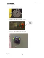
Page 99: ...ts square position Tools needed Magnetic base dial indicator carpenter s square feeler gauges or calipers 1 Determine how much out of square the machine is Cut a 24 x 24 square plate Determine its squ...

Page 100: ...MAINTENANCE Sept 2018 100 3 Set the dial on the indicator to zero 4 Turn the power switch on the CNC control off 5 Turn power off to machine Main disconnect...

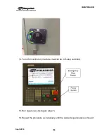
Page 101: ...rive the drive on the right hand side inside the electrical enclosure To unplug the cable squeeze the two tabs on either side of the plug and remove it from the drive 7 Turn power back on to machine 8...

Page 102: ...Y2 side of the gantry until the dial indicator reads the desired amount from step 1 10 Turn CNC control off 11 Turn power off to machine Main disconnect 12 Plug the Y2 motor lead back into the Y2 Dri...

Page 103: ...AINTENANCE Sept 2018 103 14 Turn CNC control on machine must not be in E stop condition 15 Run squareness test again step 1 16 Repeat the procedure as necessary until the desired squareness is achieve...

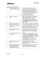
Page 104: ...ar 4 Screen is on but nothing else works Check all Emergency Stop buttons If one is pressed then release it turn power off to the control and then turn power on again 5 Arc turns off after cutting for...

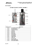
Page 105: ...EMBLY PIRANHA PART DESCRIPTION 230554 AHC ASSEMBLY FRONT PLATE 230543 AHC LIMIT SWITCH 230555 STEPPER MOTOR AHC 230556 TOP PLATE 230557 GUIDE ROD 230558 BACK PLATE 230559 GUIDE BLOCK 230560 PROX SWITC...

Page 106: ...AND SERIAL NUMBER WHEN ORDERING PARTS Sept 2018 106 AUTOMATIC HEIGHT CONTROL ASSEMBLY NOTE Specify model and serial number when ordering PIRANHA PART DESCRIPTION 230566 ANTI CRASH ASSEMBLY 230567 TORC...

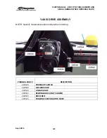
Page 107: ...PARTS Sept 2018 107 Y AXIS DRIVE ASSEMBLY NOTE Specify model and serial number when ordering PIRANHA PART DESCRIPTION 230528 PROXIMITY SWITCH 230568 MACHINE RACK 230546 LINEAR GUIDE 230544 BEARING BL...

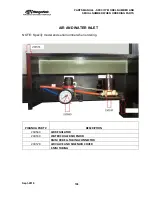
Page 108: ...EN ORDERING PARTS Sept 2018 108 AIR AND WATER INLET NOTE Specify model and serial number when ordering PIRANHA PART DESCRIPTION 230569 AIR REGULATOR 230530 WATER CHILLER SOLENOID 6MM 90 DEG TUBING CON...

Page 109: ...NOTE Specify model and serial number when ordering PIRANHA PART DESCRIPTION 230534 MATERIAL BALL ROLLER 230539 HARD LIMIT STOP 230536 CABLE TRACK PER METER 230568 MACHINE RACK 230546 LINEAR GUIDE 230...

Page 110: ...WHEN ORDERING PARTS Sept 2018 110 ELECTRICAL CABINET NOTE Specify model and serial number when ordering PIRANHA PART DESCRIPTION 230551 MICROSTEP ARC HEIGHT CONTROL 230571 GREEN PUSHBUTTON LIGHTED 230...

Page 111: ...model and serial number when ordering PIRANHA PART DESCRIPTION 230527 AC220 DC48V 230573 24V DRIVE FAULT RELAY 230574 24V CONTROL RELAY 230575 MAIN CONTACTOR 230576 MAIN BREAKER 230577 TERMINAL BLOCK...

Page 112: ...R WHEN ORDERING PARTS Sept 2018 112 MISCELLANEOUS PARTS NOTE Specify model and serial number when ordering PIRANHA PART DESCRIPTION 230602 LEVELING FOOT 230535 FAN GUARD 230604 SLAG DRAWER C 404 C 408...

Page 113: ...PARTS MANUAL SPECIFY MODEL NUMBER AND SERIAL NUMBER WHEN ORDERING PARTS Sept 2018 113 ELECTRICAL DIAGRAM MACHINES WITHOUT PIPE CUTTER...

Page 114: ...PARTS MANUAL SPECIFY MODEL NUMBER AND SERIAL NUMBER WHEN ORDERING PARTS Sept 2018 114 ELECTRICAL DIAGRAM MACHINES WITH PIPE CUTTER...

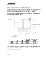
Page 115: ...t round pipe and tube from 2 through 11 5 diameter The location of the pipe cutting attachment is shown below the headstock must be located at the control end of the machine A B MACHINE WEIGHT PIPE CU...

Page 116: ...PIPE CUTTING ATTACHMENT Sept 2018 116 Components Pipe Plate Selector Switch Headstock Headstock Wrench...

Page 117: ...PIPE CUTTING ATTACHMENT Sept 2018 117 Pipe Supports Pipe Cutter Base...

Page 118: ...he forklift truck and or crane is of adequate lifting capacity and that any maneuver is undertaken safely Damage caused to the machine through incorrect or careless maneuvers is not covered under the...

Page 119: ...e Recommended a Remove securing straps chains attached to the truck bed b Obtain two straps of not less than 6 feet 1829mm with the second being 6 152mm longer than the first The below picture shows t...

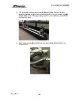
Page 120: ...87mm from the of the chuck end of the pipe cutter attachment d The second strap should be located 74 1880mm from the of the chuck end of the pipe cutter attachment The second strap should be approxima...

Page 121: ...attachment is aligned to be 9 8 250mm from the end of the plasma table as shown f The pipe cutting attachment is set parallel to the plasma table at a spacing of 16 406mm from surface of the plasma t...

Page 122: ...led using the four leveling pads so that the height of the center of the chuck is 1 00 below the slat height of the table The pipe cutting attachment must be leveled with the four leveling pads h Next...

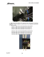
Page 123: ...t to terminal without wire behind it Wire C12 will connect to terminal in front of wire X12 Wire C13 will connect to terminal in front of wire X13 Wire C14 will connect to terminal in front of wire X1...

Page 124: ...PIPE CUTTING ATTACHMENT Sept 2018 124...

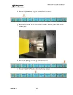
Page 125: ...t 2018 125 SWITCHING FROM PLATE CUTTING TO PIPE CUTTING 1 Change the X axis limit to allow the torch to move over the center of the pipe a From the HOME screen push F4 SETUP b Then press F2 SYSTEM to...

Page 126: ...PIPE CUTTING ATTACHMENT Sept 2018 126 c Change the X Axis SOFTLIMI value to 94 0 d Then Press the F8 SAVE to store the change e Press ESC next to go back to home screen...

Page 127: ...018 127 f Press F2 MANUAL to go to manual move screen g Move the torch in the X axis until the torch is directly above the center of the pipe h Press the ESC button to go to home screen i Press F4 SET...

Page 128: ...PIPE CUTTING ATTACHMENT Sept 2018 128 j Then press F2 SYSTEM to see the following...

Page 129: ...e NUMERATOR X 00416 using the following formula i Pipe Diameter 3 14 25 4 1 Example for 2 inch diameter pipe 2 2 3 14 25 4 159 512 round up to 160 3 Enter for NUMERATOR X 00160 l Now change the DENOMI...

Page 130: ...UTTING ATTACHMENT Sept 2018 130 n Turn off the power to the CNC Control using the Red Power Button o Move the Pipe Plate Selector Switch to PIPE p Turn on power to the CNC Control using the Red Power...

Page 131: ...OGRAMMING THE PIPE CUTTER When programming the pipe cutter the programs are generated as if the pipe is unfolded in the flat condition For example if the pipe is 4 outside diameter then the overall ci...

Page 132: ...pt 2018 132 SWITCHING FROM PIPE CUTTING TO PLATE CUTTING 1 Change the X axis limit to allow the torch to move over the center of the pipe a From the HOME screen push F4 SETUP b Then press F2 SYSTEM to...

Page 133: ...PIPE CUTTING ATTACHMENT Sept 2018 133 c Change the following values i NUMERATOR X 00416 ii DENOMINA X 00125 iii SOFTLIMI X 00061 0 d Then Press the F8 SAVE to store the change...

Page 134: ...TTING ATTACHMENT Sept 2018 134 e Turn off the power to the CNC Control using the Red Power Button f Move the Pipe Plate Selector Switch to PLATE g Turn on power to the CNC Control using the Red Power...

Page 135: ...ck over the cutting bed i The X software overtravel alarm will be on the screen but X can move in the minus direction of the table This alarm will clear once the torch position is less than the normal...

Page 136: ...PIPE CUTTING ATTACHMENT Sept 2018 136...

Page 137: ...er Mist Chiller provides additional cooling of the work piece that may in some cases reduce warpage especially in thinner material This option consists of a water chiller solenoid valve and spray tube...

Page 138: ...the tee fitting to the water solenoid located next to the incoming air regulator on the machine using 8 mm tubing DO NOT CONNECT THE INLET OF THE CHILLER TO A WATER SUPPLY 2 Bend the copper tubing so...

Page 139: ...r switch on 2 Press the lighted WATER CHILLER pushbutton on the CNC control so that it lights up The chiller will now spray as the plasma torch is cutting To disengage the chiller feature simply turn...

Page 140: ...WATER MIST CHILLER Sept 2018 140...

Page 141: ...Drive but it functions as a license key to unlock the software The FastCAM software cannot run without the dongle in place in the computer s USB port 3 Installation and Startup Instructions The FastC...

Page 142: ...er open this file holder 3 Find the file open this file change on the 6th row to 4 save If your system do not allow you to change the file you can copy the file to other disc or USB make changes and s...

Page 143: ...CAM software you need to finish INITIAL FASTCAM SETUPS attached with this file before you start to nest import a part drawing C How to edit a part drawing 1 Open FastCAM holder open FastCAM 2 The tool...

Page 144: ...APPENDIX A FastCAM SETUP Sept 2018 144 4 Choose the functions you need and Enter...

Page 145: ...D How to create a part How to use FastCAM to draw a part We will draw a 4 square with 1 diameter round hole To create a part drawing with FastCAM 1 Open FastCAM holder open FastCAM 2 The tool bar on t...

Page 146: ...AM SETUP Sept 2018 146 i input the Radius of Circle and Enter ii Your mouse become a white cross click the right button of mouse iii choose Absolute co ords input the absolute co ordinates of circle c...

Page 147: ...y you will see a 4 square with a 1 round hole right in the middle 6 Push Files on the top left of the tool bar choose Save to save the part in a CAM file or DXF Save to save the part in a DXF file The...

Page 148: ...ettings page comes out 3 under Process on top left choose CUTTING LEFT BOTH 4 under External Entry set the Entry and Exit according to your need Entry is lead in and Exit is the lead out Normally the...

Page 149: ...ength of extension is same as the length of entry exit and the blank to the right of the length of extension is the angle of extension line to entry exit line our default number is 1 181 which means 3...

Page 150: ...ead in out location i Open FastNEST click on the right of the tool bar on top ii click you will see FastPATH Settings page comes out iii on top left in Position you can select the general location of...

Page 151: ...you are satisfied with the new lead in out position click on the top left and then you can resume nesting If you want to cancel editing the lead in out position click 3 Move lead in out when you gener...

Page 152: ...llowing the steps of ii and iii of step 2 here above when you click you can rename your NC output you just generated G How to select sheet size type and shape 1 open FastCAM file holder and open FastN...

Page 153: ...stCAM 1 Go to your system disc disc C and find Fastcam file holder In disc C you find then double click Program Files x86 2 Then you will find file holder open this file holder 3 Open 4 optional Delet...

Page 154: ...APPENDIX A FastCAM SETUP Sept 2018 154...

Page 155: ...le 3 PLASMA create a part program to cut for the complete operation 1 Double click FastCAM file holder then double click FastNEST 2 Finish all the initial setup by following the steps in the file 3 CR...

Page 156: ...st as many Part A to this sheet as possible If you need to nest multiple parts A B and C to the same sheet and you definitely need Part A as soon as possible you need part B in 2 days and Part C in 2...

Page 157: ...the yellow frame For example i Click one the part you want to move with left button of mouse keep holding left it and do not let it go until the part move the better new spot ii The broken yellow lin...

Page 158: ...n yellow lines will move to left down right up as much as the limit goes the Part to Part and Part to Plate distances can be set in FastNEST Parameters you can find the page by clicking on the tool ba...

Page 159: ...APPENDIX A FastCAM SETUP Sept 2018 159...

Page 160: ...en you will see a page comes up on which you can rename the nesting file TXT file save and copy that TXT file to your USB bright your USB to your PARANA plasma machine you are ready to start cutting J...

Page 161: ...the right in Preselect answers check Resequence then every time when you generate output you will be able to edit part cutting sequence 3 you can choose certain sequence or indicate the sequence by cl...

Page 162: ...ool bar on top a Plate cutoff page will come up 2 On Plate cutoff page i Trim Line Type normally we choose Contoured ii Minimum remnant width the smallest width length of sheet you can use iii Trim li...

Page 163: ...oose Y and input file path where you want to save all the Remnant CAM files or simply click Enter 6 To use the remnant sheet i click then choose Remnant CAM ii click go to the same file path to find t...

Page 164: ...APPENDIX A FastCAM SETUP Sept 2018 164...

Page 165: ...The following table shows all of the available parametric shapes with their customizable values labeled See pg XX for instruction on how to cut a single part or create a nested program using the param...

Page 166: ...APPENDIX B Parametric Shape Library Sept 2018 166 7 Chamfer 8 Roof Rec 2 9 Flange Single Hole 10 Octagon 11 Protrud 12 Ingconca...

Page 167: ...APPENDIX B Parametric Shape Library Sept 2018 167 13 Sector Ri 14 Circular 15 Quadrate 16 U Shape...

Page 168: ...PENDIX B Parametric Shape Library Sept 2018 168 17 Define T 18 Curved T 19 Flange Hole 4 Hole Flange 20 6 hole Flange 21 Impeller 22 2 Hole Flange R R OUTR2 R OUT HOLE R 2 PLACES R L OUT R1 R L HOLE R...

Page 169: ...APPENDIX B Parametric Shape Library Sept 2018 169 Library 2 1 Bridge1 Do not use 2 Bridge2 Do not use 3 Bridge3 Do not use 4 Bridge4 Do not use 5 Arch Do not use 6 Groove 7 Diam 8 Hole2...

Page 170: ...APPENDIX B Parametric Shape Library Sept 2018 170 9 Fla X 10 Lad 11 Rec 12 Rec8...

Page 171: ...APPENDIX B Parametric Shape Library Sept 2018 171 13 Tria 14 Rec 15 Rec c 16 Rec H 17 Circle2 18 Circle3...

Page 172: ...APPENDIX B Parametric Shape Library Sept 2018 172 19 Rec 20 Rec c 21 Circle4 22 Rec...

Page 173: ...APPENDIX B Parametric Shape Library Sept 2018 173 23 Rec 24 Pol 25 Hole Circle 26 Pol Do not use...

Page 174: ...APPENDIX B Parametric Shape Library Sept 2018 174...

Page 175: ...E 4 25 2017 Added RESQUARING Procedure in MAINTENANCE section 6 1 2017 Added information on Powermax 105 and 125 6 1 2017 New Electrical Schematic 6 1 2017 Added alternate procedure for setting pierce...

Page 176: ...APPENDIX C Manual Revisions Sept 2018 176...

Reviews: