background image

Basic playback

05

55

En

5

Select the ‘Passcode’ setting you want.

Select the same passcode as the 

Bluetooth


wireless technology device you wish to 
connect.

•  

0000

/

1234

/

8888

 – Select the passcode 

from these options. These are the 
passcodes that can be used in most cases.

Others

 – Select to use a passcode other 

than those mentioned above.

6

If you selected Others in step 5, enter the 

passcode.

Use 

/

 to select a number and 

/

 to 

move the cursor.

7

Follow the instructions displayed on the 

GUI screen to conduct pairing with the 

Bluetooth

 wireless technology device.

Switch on the 

Bluetooth

 wireless technology 

device that you want to make pair, place it near 
the receiver and set it to the pairing mode.

8

Check to see that the 

Bluetooth

 ADAPTER 

is detected by the 

Bluetooth

 wireless 

technology device.

When the Bluetooth wireless technology device 
is connected:

CONNECTED

 appears in the receiver display.

1


When the Bluetooth wireless technology device 
is not connected:

Go back to the passcode setting in step 5. In 
this case, perform the connection operation 
from the 

Bluetooth

 wireless technology device.

9

From  the 

Bluetooth

 wireless technology 

device list, select 

Bluetooth

 ADAPTER and 

enter the Passcode selected in step 5.

2

Listening to music contents of a 

Bluetooth

 wireless technology 

device with your system

1

Press ADAPTER on the remote control to 

switch the receiver to ADAPTER PORT input.

3

2

Perform the connection operation from 

the side of the 

Bluetooth

 wireless technology 

device to the 

Bluetooth

 ADAPTER.

3

Start playback of music contents stored 

on the 

Bluetooth

 wireless technology device.

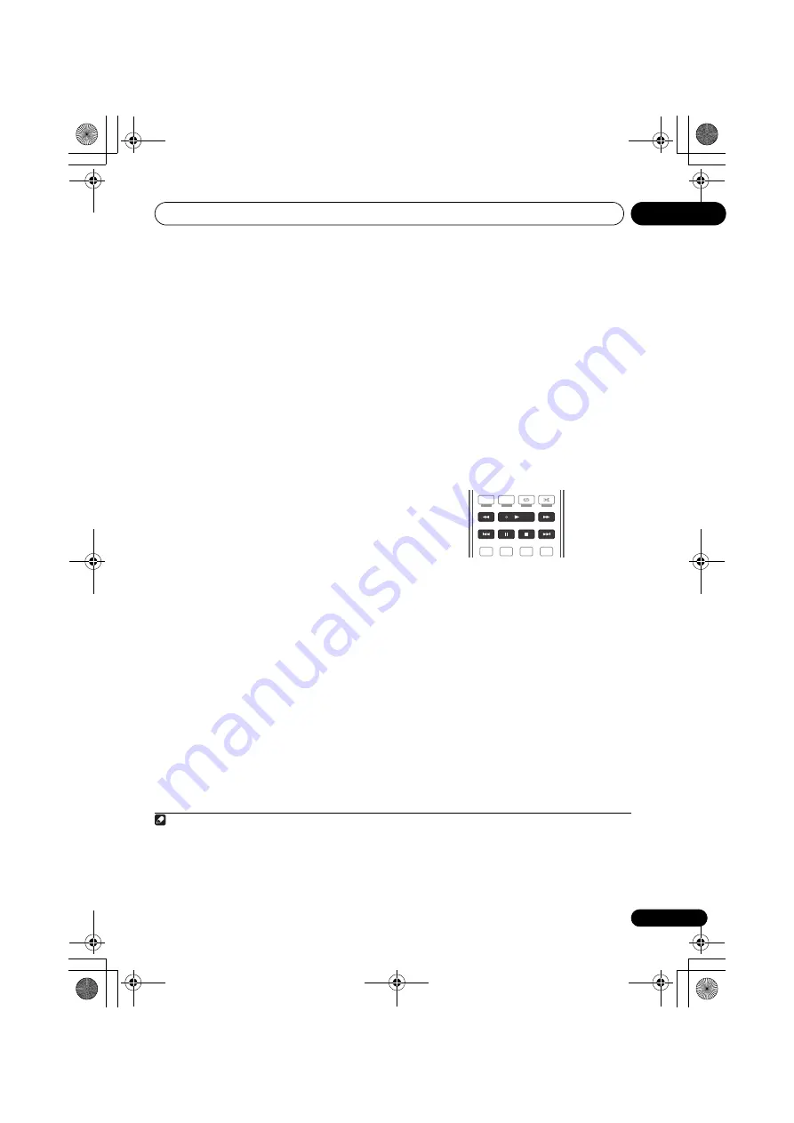
This receiver’s remote control buttons can be 
used for basic playback of files stored on 

Bluetooth

 wireless technology devices.

4

The 

Bluetooth

®

 word mark and logos are 

registered trademarks owned by Bluetooth 
SIG, Inc. and any use of such marks by Pioneer 
Corporation is under license. Other 
trademarks and trade names are those of their 
respective owners.

Note

1 The system can display alphanumeric characters only. Other characters may not be displayed correctly.
2 The passcode may in some cases be referred to as “passkey” or PIN code.
3 When the 

Bluetooth

 ADAPTER is not plugged into the 

ADAPTER PORT

NO ADAPTER 

will be displayed if 

ADAPTER 

PORT

 input is selected.

4 • 

Bluetooth

 wireless technology device should be compatible with AVRCP profile.

• Depending on the 

Bluetooth

 wireless technology device you use, operation may differ from what is shown in the 

remote control buttons.

S.RETRIEVER

MIDNIGHT

TV / DTV

MPX

PQLS

PHASE  CTRL

STATUS

PGM

MEMORY

MENU

AUDIO

HDD

DVD

2

1

3

VSX-31_30_UC.book  55 ページ  2010年8月25日 水曜日 午前9時28分

Summary of Contents for Elite VSX-30

Page 1: ...audio video multi channel receiver VSX 31_30_UC book 1 ページ 2010年8月25日 水曜日 午前9時28分 ...

Page 2: ... generates uses and can radiate radio frequency energy and if not installed and used in accordance with the instructions may cause harmful interference to radio communications However there is no guarantee that interference will not occur in a particular installation If this equipment does cause harmful interference to radio or television reception which can be determined by turning the equipment ...

Page 3: ...at the power cord can be easily unplugged from the AC outlet in case of an accident To avoid fire hazard the power cord should also be unplugged from the AC outlet when left unused for a long period of time for example when on vacation D3 4 2 2 2a _A1_En Caution To prevent fire hazard the Class 2 Wiring Cable should be used for connection with speaker and should be routed away from hazards to avoi...

Page 4: ...ther audio components 30 About the WMA9 Pro decoder 30 Connecting AM FM antennas 31 Connecting external antennas 31 MULTI ZONE setup 32 Making MULTI ZONE connections 32 Connecting Optional Bluetooth ADAPTER 33 Connecting a SiriusConnect Tuner 34 Connecting to the network through LAN interface 34 Connecting an HDMI equipped component to the front panel input 35 Connecting to the front panel video t...

Page 5: ...ONE controls 77 Making an audio or a video recording 78 Reducing the level of an analog signal 79 Using the sleep timer 79 Dimming the display 79 Checking your system settings 79 Resetting the system 80 Default system settings 80 09 Controlling the rest of your system Operating multiple receivers 81 Setting the remote to control other components 81 Selecting preset codes directly 82 Programming si...

Page 6: ...ormation Troubleshooting 112 Power 112 No sound 113 Other audio problems 115 Video 116 Settings 117 Professional Calibration EQ graphical output 118 Display 118 Remote control 119 HDMI 120 Important information regarding the HDMI connection 121 USB interface 122 ADAPTER PORT 123 Internet radio 123 SIRIUS radio messages 124 About SIRIUS 124 About iPod 125 Surround sound formats 125 Dolby 125 DTS 12...

Page 7: ...k components page 25 Connecting AM FM antennas page 31 Plugging in the receiver page 40 5 Power On 6 Changing the OSD display language OSD Language page 41 7 MCACC speaker settings Automatically conducting optimum sound tuning Auto MCACC page 41 8 The Input Setup menu page 44 When using connections other than the recommended connections 9 Basic playback page 46 10 Adjusting the sound and picture q...

Page 8: ...comes hot when the power is on or right after it is turned off and could cause burns Loading the batteries The batteries included with the unit are to check initial operations they may not last over a long period We recommend using alkaline batteries that have a longer life CAUTION Incorrect use of batteries may result in such hazards as leakage and bursting Observe the following precautions Never...

Page 9: ...r display See Display on page 11 7 Indicators ADVANCED MCACC Lights when EQ is set to ON in the AUDIO PARAMETER menu PQLS Lights when the PQLS feature is active page 70 HDMI Blinks when connecting an HDMI equipped component lights when the component is connected page 25 SPEAKERS AUTO ALC DIRECT STEREO STANDARD LISTENING MODE ADV SURROUND DIRECT CONTROL iPod iPhone CONTROL ON OFF MULTI ZONE PQLS HD...

Page 10: ...ront Stage Surround Advance modes page 64 STANDARD Press for Standard decoding and to switch between the various 2 Pro Logic IIx and Neo 6 options page 61 ADV SURROUND Switch between the various surround modes page 63 12 iPod iPhone DIRECT CONTROL Change the receiver s input to the iPod and enable iPod operations on the iPod page 48 13 MCACC SETUP MIC jack Connect the supplied microphone page 41 1...

Page 11: ...ts during playback of PCM signals MSTR Lights during playback of DTS HD Master Audio signal 4 MULTI ZONE Lights when the MULTI ZONE feature is active page 77 5 SOUND Lights when any of the Midnight Loudness or tone controls feature is selected page 72 Lights when Dialog Enhancement is switched on 6 S RTRV Lights when the Sound Retriever function is active page 73 7 Listening mode indicators AUTO S...

Page 12: ...ave selected 14 Scroll indicators Light when there are more selectable items when making the various settings 15 Speaker indicators Indicates the speaker terminal A and or B to which audio signal output is currently set page 77 16 SLEEP Lights when the receiver is in sleep mode page 79 17 Matrix decoding format indicators 2PRO LOGIC IIx This lights to indicate 2 Pro Logic II 2 Pro Logic IIx decodi...

Page 13: ...T Select the TV input signal CH Select channels VOL Adjust the volume on your TV 6 Receiver controls Press first to access AUDIO PARAMETER Use to access the Audio options page 72 VIDEO PARAMETER Use to access the Video options page 75 HOME MENU Use to access the Home Menu pages 41 44 68 90 104 and 110 RETURN Press to confirm and exit the current menu screen RECEIVER LISTENING MODE AUTO ALC DIRECT ...

Page 14: ...Switches between stereo playback and Front Stage Surround Advance modes page 64 STANDARD Press for Standard decoding and to switch between the various 2 Pro Logic IIx and Neo 6 options page 61 ADV SURR Switch between the various surround modes page 63 10 Remote control LED Lights when a command is sent from the remote control page 81 11 TV CTRL Set the preset code of your TV s manufacturer when co...

Page 15: ...V SAT AM LOOP FM UNBAL 75 COMPONENT VIDEO AUDIO PRE OUT ANTENNA OPTICAL SIRIUS ADAPTERPORT VIDEO RS 232C IR CONTROL SPEAKERS SPEAKERS MONITOR OUT LAN COAXIAL BD IN IN IN IN IN OUT 10 100 IN IN 1 IN 2 1 IN 1 IN 2 1 4 2 3 4 IN 1 A IN 2 B IN OUT IN OUT AC IN OUTPUT12V TOTAL50mAMAX 1 2 12 V TRIGGER VSX 31 HDMI ASSIGNABLE PB PR ASSIGNABLE ASSIGNABLE ASSIGNABLE DVD DVR BDR DVD Y PB PR Y PB PR Y L R R FR...

Page 16: ...w are assigned by default to the receiver s different input terminals Refer to The Input Setup menu on page 44 to change the assignments if other connections are used Input function Input Terminals Digital HDMI Component DVD COAX 1 IN 1 BD BD TV SAT OPT 1 DVR BDR OPT 2 IN 2 HDMI 1 HDMI 1 HDMI 2 HDMI 2 HDMI 3 HDMI 3 HDMI 4a a VSX 31 only HDMI 4 HDMI 5a front panel HDMI 5 CD COAX 2a VSX 31_30_UC boo...

Page 17: ... produces a more true to life sound from above B 7 1 channel surround system Front wide Speaker System setting Normal SB FW This plan replaces the left and right front height speakers shown in A with the left and right front wide speakers FWL FWR 1 This surround system produces a true to life sound over a wider area C 7 1 channel surround system Speaker B connection Speaker System setting Speaker ...

Page 18: ...ing on page 105 Sound does not come through simultaneously from the front height front wide speaker B and surround back speakers Output speakers are different depending on the input signal or listening mode Other speaker connections Your favorite speaker connections can be selected even if you have fewer than 5 1 speakers except front left right speakers When not connecting a subwoofer connect spe...

Page 19: ...o 3 m 6 ft to 9 ft apart at equal distance from the TV If you re going to place speakers around your CRT TV use shielded speakers or place the speakers at a sufficient distance from your CRT TV If you re using a center speaker place the front speakers at a wider angle If not place them at a narrower angle Place the center speaker above or below the TV so that the sound of the center channel is loc...

Page 20: ...insert exposed wire 3 Tighten terminal B Speaker terminals 1 Twist exposed wire strands together 2 Push open the tabs and insert exposed wire 3 Release the tabs Banana plug connections A Speaker terminals only If you want to use speaker cables terminated with banana plugs screw the speaker terminal fully shut then plug the banana plug into the end of the speaker terminal Important Please refer to ...

Page 21: ...SIRIUS ADAPTERPORT VIDEO RS 232C IR CONTROL SPEAKERS SPEAKERS MONITOR OUT LAN COAXIAL BD IN IN IN IN IN OUT 10 100 IN IN 1 IN 2 1 IN 1 IN 2 1 4 2 3 4 IN 1 A IN 2 B IN OUT IN OUT AC IN OUTPUT12V TOTAL50mAMAX 1 2 12 V TRIGGER SUBWOOFER LINELEVEL INPUT Front left Subwoofer Center Surround right Surround back left Surround back right Front right Surround left 7 1 ch surround setting Not connected Surr...

Page 22: ...etting makes no difference To bi wire a speaker connect two speaker cords to the speaker terminal on the receiver Using a banana plug for the second connection is recommended CAUTION Don t connect different speakers from the same terminal in this way When bi wiring as well heed the cautions for bi amping shown at the left HDMI ASSIGNABLE PB PR ASSIGNABLE ASSIGNABLE ASSIGNABLE DVD DVR BDR DVD Y PB ...

Page 23: ...to do this Speaker B setup You can listen to stereo playback in another room 1 Connect a pair of speakers to the front height speaker terminals See Connecting the speakers on page 20 2 Select Speaker B from the Speaker System menu See Speaker system setting on page 105 to do this Bi Amping setup Bi amping connection of the front speakers for high sound quality with 5 1 channel surround sound 1 Con...

Page 24: ...ventional digital audio Digital Optical RCA Analog White Red Conventional analog audio Note 1 If the video signal does not appear on your TV try adjusting the resolution settings on your component or display Note that some components such as video game units have resolutions that may not be converted In this case try switching Digital Video Conversion in Setting the Video options on page 75 OFF Th...

Page 25: ... connect the receiver and TV with audio cables HDMI ASSIGNABLE PB PR ASSIGNABLE ASSIGNABLE ASSIGNABLE DVD DVR BDR DVD Y PB PR Y PB PR Y L R R FRONT CENTER SURROUND L R ZONE 2 OUT DVR BDR DVD OUT IN CD R TAPE OUT IN IN CD IN TV SAT IN VIDEO IN DVR BDR OUTPUT CD SUBWOOFER TV SAT AM LOOP COMPONENT VIDEO AUDIO PRE OUT ANTENNA OPTICAL A VIDEO IR CONTROL SPEAKERS MONITOR OUT LAN COAXIAL BD IN IN IN IN I...

Page 26: ...with DVI equipped components compatible with both DVI and High Bandwidth Digital Content Protection HDCP If you choose to connect to a DVI connector you will need a separate adaptor DVI HDMI to do so A DVI connection however does not support audio signals Consult your local audio dealer for more information If you connect a component that is not compatible with HDCP an HDCP ERROR message is displa...

Page 27: ...R DVD Y PB PR Y PB PR Y L R R FRONT CENTER SURROUND L R L ZONE 2 OUT DVR BDR DVD OUT IN CD R TAPE OUT IN IN CD IN TV SAT IN VIDEO IN DVR BDR OUTPUT 5 CD SUBWOOFER TV SAT AM LOOP F COMPONENT VIDEO AUDIO PRE OUT ANTENNA OPTICAL AD VIDEO IR CONTROL SPEAKERS MONITOR OUT LAN COAXIAL BD IN IN IN IN IN OUT 10 100 IN 1 IN 2 1 IN 1 IN 2 1 4 2 3 4 IN 1 A IN 2 IN OUT IN OUT RS 232C OUTPUT12V TOTAL50mAMAX 1 2...

Page 28: ...NABLE ASSIGNABLE ASSIGNABLE DVD DVR BDR DVD Y PB PR Y PB PR Y L R R FRONT CENTER SURROUND L R ZONE 2 OUT DVR BDR DVD OUT IN CD R TAPE OUT IN IN CD IN TV SAT IN VIDEO IN DVR BDR OUTPU CD SUBWOOFER TV SAT AM LOOP COMPONENT VIDEO AUDIO PRE OUT ANTENNA OPTICAL VIDEO IR CONTROL SPEAKERS MONITOR OUT LAN COAXIAL BD IN IN IN IN IN OUT 10 100 IN 1 IN 2 1 IN 1 IN 2 1 4 2 3 4 IN 1 A IN 2 IN OUT IN OUT RS 232...

Page 29: ... the digital connection is for playback only ASSIGNABLE ASSIGNABLE DVD DVR BDR R FRONT CENTER SURROUND SURROU L R L R DVR BDR DVD OUT IN CD R TAPE OUT IN IN CD IN TV SAT IN VIDEO IN OUTPUT 5 V 100 mA MAX CD SUBWOOFER TV SAT AM LOOP FM UNBAL 75 PRE OUT ANTENNA OPTICAL ADAPTERPOR IR CONTROL SPEAKERS LAN COAXIAL N IN IN OUT 10 100 IN 1 IN 2 2 3 4 IN 1 A IN 2 IN OUT IN OUT T12V 0mAMAX 2 RIGGER VIDEO O...

Page 30: ...9 Pro encoded audio using HDMI coaxial or optical digital connection when connected to a WMA9 Pro compatible player However the connected DVD player set top box etc must be able to output WMA9 Pro format audio signals through a coaxial or optical digital output ASSIGNABLE ASSIGNABLE DVD DVR BDR R FRONT CENTER SURROUND SURROUND L R L R CD R TAPE OUT IN CD IN TV SAT IN VIDEO IN OUTPUT 5 V 100 mA MAX...

Page 31: ...g the loop to the stand Make sure the reception is clear 4 Place the AM antenna on a flat surface and in a direction giving the best reception 5 Connect the FM wire antenna into the FM antenna socket For best results extend the FM antenna fully and fix to a wall or door frame Don t drape loosely or leave coiled up Connecting external antennas To improve FM reception connect an external FM antenna ...

Page 32: ...erminals ZONE 2 on page 33 for the sub zone MULTI ZONE listening options The following table shows the signals that can be output to ZONE 2 Basic MULTI ZONE setup ZONE 2 1 Connect a separate amplifier to the AUDIO ZONE 2 OUT jacks and a TV monitor1 to the VIDEO ZONE 2 OUT jack both on this receiver 2 Connect a pair of speakers to the sub zone amplifier Note 1 VSX 30 model cannot connect the TV mon...

Page 33: ...sic on page 54 Important Do not move the receiver with the Bluetooth ADAPTER connected Doing so could cause damage or faulty contact ABLE D SURROUND BACK L R L OUTPUT 5 V 500 mA MAX Single OP FM UNBAL 75 AL SIRIU ADAPTERPORT IN HDMI ASSIGNABLE PB PR ASSIGNABLE DVD Y PB PR Y PB PR Y L R ZONE 2 OUT DV OUT DVR BDR COMPONENT VIDEO AUDIO VIDEO MONITOR OUT BD IN IN IN 1 IN 1 IN 2 1 4 2 RS 232C OUTPUT12V...

Page 34: ...function of your router In case your router does not have the built in DHCP server function it is necessary to set up the network manually For details see Network Setup menu on page 108 LAN terminal specifications LAN terminal Ethernet jack 10BASE T 100BASE TX ASSIGNABLE VR BDR URROUND SURROUND BACK FRONT HEIGHT WIDE L R L R L OUTPUT 5 V 100 mA MAX Single AM LOOP FM UNBAL 75 OPTICAL SIRIUS ADAPTER...

Page 35: ... this terminal Connecting to the front panel video terminal VSX 30 only Front video connections are accessed via the INPUT SELECTOR dial front panel or INPUT SELECT buttons remote control There are standard audio video jacks Hook them up the same way you made the rear panel connections CONTROL ON OFF MASTER VOLUME MCACC SETUP MIC VIDEO CAMERA iPod iPhone USB HDMI 5 Video camera etc CONTROL ON OFF ...

Page 36: ...nt panel of this receiver It is also possible to connect using the cable included with the iPod but in this case it is not possible to view pictures via the receiver For the cable connection also refer to the operating instructions for your iPod VSX 31 VSX 30 MASTER VOLUME MCACC SETUP MIC VIDEO CAMERA iPod iPhone USB HDMI 5 CONTROL ON OFF MENU iPod iPod cable supplied MASTER VOLUME CONTROL ON OFF ...

Page 37: ...ansferred from this receiver to a USB device and by connecting the USB device to a computer the data is imported via the MCACC software in the computer The MCACC software to output the results is available from the support area of the Pioneer website http www pioneerelectronics com PUSA Home Entertainment Custom Install Instructions for using the software are also available here If you have any qu...

Page 38: ...er components with this unit s sensor below to connect to the CONTROL jacks instead of the IR OUT jack Note 1 Remote operation may not be possible if direct light from a strong fluorescent lamp is shining on the IR receiver remote sensor window Note that other manufacturers may not use the IR terminology Refer to the manual that came with your component to check for IR compatibility If using two r...

Page 39: ...g remote control 2 Connect the CONTROL OUT jack of that component to the CONTROL IN jack of another Pioneer component Use a cable with a mono mini plug on each end for the connection Continue the chain in the same way for as many components as you have Note 1 If you want to control all your components using this receiver s remote control see Setting the remote to control other components on page 8...

Page 40: ...circuit or electric shock Do not place the unit a piece of furniture or other object on the power cord or pinch the cord in any other way Never make a knot in the cord or tie it with other cables The power cords should be routed so that they are not likely to be stepped on A damaged power cord can cause a fire or give you an electric shock Check the power cord once in a while If you find it damage...

Page 41: ...m sound tuning Auto MCACC The Auto MCACC Setup measures the acoustic characteristics of your listening area taking into account ambient noise speaker connection and speaker size and tests for both channel delay and channel level After you have set up the microphone provided with your system the receiver uses the information from a series of test tones to optimize the speaker settings and equalizat...

Page 42: ... leave it set to NO Note 1 Install the microphone on a stable floor Placing the microphone on any of the following surfaces may make accurate measurement impossible Sofas or other soft surfaces High places such as tabletops and sofa tops MASTER VOLUME MCACC SETUP MIC VIDEO CAMERA iPod iPhone USB HDMI 5 CONTROL ON OFF Microphone Tripod VSX 31 2 If you leave the GUI screen for over five minutes the ...

Page 43: ...d continue If Reverse Phase is displayed the speaker s wiring and may be inverted Check the speaker connections 2 If the connections were wrong turn off the power disconnect the power cord then reconnect properly After this perform the Full Auto MCACC procedure again If the connections were right select GO NEXT and continue 7 Make sure OK is selected then press ENTER A progress report is displayed...

Page 44: ...elect menu items Press RETURN to confirm and exit the current menu 3 Select System Setup from the Home Menu 4 Select Input Setup from the System Setup menu 5 Select the input function that you want to set up The default names correspond with the names next to the terminals on the rear panel such as DVD which in turn correspond with the names on the remote control 6 Select the input s to which you ...

Page 45: ...ill return to the System Setup menu Input function default and possible settings The terminals on the receiver generally correspond to the name of one of the input functions If you have connected components to this receiver differently from or in addition to the defaults below see The Input Setup menu on page 44 to tell the receiver how you ve connected up The dots indicate possible assignments No...

Page 46: ...eck on the front panel display whether or not multi channel playback is being performed properly When using a surround back speaker PLIIx MOVIE is displayed when playing Dolby Digital signals and DTS Neo 6 is displayed when playing DTS 5 1 channel signals If the display does not correspond to the input signal and listening mode check the connections and settings 4 Use the volume control to adjust ...

Page 47: ...screen of your TV connected to this receiver 3 You can also control all operations for music in the front panel display of this receiver Note 1 This system is compatible with the audio and video of the iPod nano audio only for the iPod nano 1G 2G iPod fifth generation audio only iPod classic iPod touch and iPhone However some of the functions may be restricted for some models The system is not com...

Page 48: ...ote control to the iPod USB operation mode Switching the iPod controls3 You can switch over the iPod controls between the iPod and the receiver 1 Press iPod CTRL to switch the iPod controls This enables operation and display on your iPod and this receiver s remote control and GUI screen become inactive 2 Press iPod CTRL again to switch back to the receiver controls Tip Change the receiver s input ...

Page 49: ...e flash memory drives particularly key drives and digital audio players MP3 players of format FAT12 16 32 It is not possible to connect this unit to a personal computer for USB playback Pioneer cannot guarantee compatibility operation and or bus power with all USB mass storage devices and assumes no responsibility for any loss of data that may occur when connected to this receiver 2 Make sure the ...

Page 50: ...Theme Add various effects to the slideshow Interval Set the interval for switching the photos This may not be available depending on the Theme setting BGM Play music files stored on the USB device while displaying photos Music Select Select the folder containing the music files to be played when BGM is set to ON 3 When you re finished press RETURN You will return to the USB Top menu Note 1 Photo f...

Page 51: ...R Supported Supported WAV wav LPCM Sampling frequency 32 kHz 44 1 kHz 48 kHz Quantization bitrate 8 bit 16 bit Channel 2 ch Monaural WMA wma WMA8 9b b Files encoded using Windows Media Codec 9 may be playable but some parts of the specification are not supported specifically Pro Lossless Voice Sampling frequency 8 kHz to 48 kHz Quantization bitrate 16 bit Channel 2 ch Bitrate 8 kbps to 320 kbps VB...

Page 52: ...his feature uses Neural Surround technologies to achieve optimal surround sound from FM radio While listening to FM radio press AUTO ALC DIRECT for Neural Surround listening See Auto Surround ALC and Stream Direct with different input signal formats on page 126 for more on this The NEURAL SURROUND mode can be selected also with STANDARD Tuning directly to a station Sometimes you ll already know th...

Page 53: ...following characters for a name up to eight characters long ABCDEFGHIJKLMNOPQRSTUVWXYZ abcdefghijklmnopqrstuvwxyz 0123456789 _ space Use to select a character to set the position and ENTER to confirm your selection Tip To erase a station name simply repeat steps 1 to 3 and input eight spaces instead of a name Once you have named a station preset you can press DISP when listening to a station to sw...

Page 54: ...he system or any time pairing data is cleared The pairing step is necessary to register the Bluetooth wireless technology device to enable Bluetooth communications 2 For more details see also the operating instructions of your Bluetooth wireless technology device 1 Press then press HOME MENU 2 Select System Setup then press ENTER 3 Select Other Setup then press ENTER 4 Select Pairing Bluetooth Dev...

Page 55: ...step 5 2 Listening to music contents of a Bluetooth wireless technology device with your system 1 Press ADAPTER on the remote control to switch the receiver to ADAPTER PORT input 3 2 Perform the connection operation from the side of the Bluetooth wireless technology device to the Bluetooth ADAPTER 3 Start playback of music contents stored on the Bluetooth wireless technology device This receiver s...

Page 56: ...lected item Depending on the Internet line conditions the sound may not be smooth when playing Internet radio To return to the list screen press RETURN 3 Programming the Internet radio stations By programming the Internet radio stations you wish to listen to onto this receiver you will be able to select those Internet radio stations You can program up to 24 stations There are two methods of progra...

Page 57: ...d 3 Enter the title and URL of the Internet radio station you wish to program then press Update The entered information will be transmitted to the receiver The connection to the URL designated from the computer will be confirmed If connection is successful Connection OK will be displayed on screen and the selected Internet radio station will begin playing via this receiver If the connection failed...

Page 58: ... not available in Alaska and Hawaii Press SIRIUS to switch to the SIRIUS input 1 For best reception you may need to move the SiriusConnect tuner antenna near a window refer to the manual for the SiriusConnect Home tuner for antenna placement recommendations If after pressing SIRIUS the display shows Antenna Error try disconnecting the antenna and reconnecting 2 If the display shows Check Sirius Tu...

Page 59: ...by genre on page 58 2 Press T EDIT The display shows a blinking memory class 3 Press CLASS to select one of the seven classes then press to select the channel preset you want You can also use the number buttons to select a preset 4 Press ENTER After pressing ENTER the preset class and number stop blinking and the receiver stores the SIRIUS channel Tip You can also press MEMORY during reception dis...

Page 60: ... select channels you would like to place under parental lock Channels put under parental lock are not displayed in the Channel Guide but may be accessed by directly inputting their channel number and providing the parental lock password Antenna Aiming Check the strength of satellite and terrestrial reception Memory Recall Use to browse your saved song information see Tip above Password Set Set the...

Page 61: ...y see Listening in stereo on page 63 for more on this ALC In the Auto level control ALC mode this receiver equalizes playback sound levels Tip When ALC is selected the effect level can be adjusted using the EFFECT parameter in Setting the Audio options on page 72 Listening in surround sound Using this receiver you can listen to any source in surround sound However the options available will depend...

Page 62: ...ogic IIx MUSIC See above Dolby Digital EX Creates surround back channel sound for 5 1 channel sources and provides pure decoding for 6 1 channel sources like Dolby Digital Surround EX DTS ES Allows you to hear 6 1 channel playback with DTS ES encoded sources DTS Neo 6 Allows you to hear 6 1 channel playback with DTS encoded sources 2 Pro Logic IIz HEIGHT See above3 WIDE SURROUND MOVIE See above4 W...

Page 63: ...istening mode is selected the effect level can be adjusted using the EFFECT parameter in Setting the Audio options on page 72 Listening in stereo When you select STEREO you will hear the source through just the front left and right speakers and possibly your subwoofer depending on your speaker settings Multichannel sources are downmixed to stereo While listening to a source press then press STEREO...

Page 64: ...in the front panel display to see how the source is being processed AUTO SURROUND See Auto playback on page 61 ALC Listening in Auto level control mode page 61 DIRECT Plays back sound from the source with the least modification next to PURE DIRECT With DIRECT the only modifications added to PURE DIRECT playback are calibration of the sound field by the MCACC system and the Phase Control effect PUR...

Page 65: ... the signal being decoded see Display on page 11 Note 1 Different presets might also have separate calibration settings for the same listening position depending on how you re using your system These presets can be set in Automatically conducting optimum sound tuning Auto MCACC on page 41 or Automatic MCACC Expert on page 91 either of which you should have already completed 2 These settings have n...

Page 66: ...signal If a crest of a wave meets a trough then the sound will be out of phase and an unreliable sound image will be produced The PHASE CONTROL feature is available even when the headphones are plugged in If your subwoofer has a phase control switch set it to the plus sign or 0 However the effect you can actually feel when PHASE CONTROL is set to ON on this receiver depends on the type of your sub...

Page 67: ...erent type of HDMI cable is used For details about concrete operations settings etc refer to also the operating instructions for each component Making Control with HDMI connections You can use synchronized operation for a connected TV and up to six VSX 31 model BD HDMI 1 to 5 front panel four VSX 30 model BD HDMI 1 to 3 other components Be sure to connect the TV s audio cable to the audio input of...

Page 68: ...de setting you want Choose whether you want to enable HDMI for all linked functions or the PQLS function only However Display Power Off will activate the settings set forth in step 7 below ALL Enabled for all linked functions PQLS Enabled only for the PQLS function When PQLS is selected link functions other than the PQLS function may not work properly If you wish to use all link functions select A...

Page 69: ...e played through the receiver from the TV s menu screen etc This receiver will power up and switch to the synchronized amp mode When the synchronized amp mode is canceled the receiver s power turns off if you were viewing an HDMI input or a TV program on the TV When in the synchronized amp mode the synchronized amp mode is canceled if an operation that produces sound from the TV is performed from ...

Page 70: ...QLS Precision Quartz Lock System is a digital audio signal transfer control technology using the Control with HDMI function It offers higher quality audio playback by controlling audio signals from the receiver to a PQLS compatible player etc This enables removing jitter that has a negative effect on the quality of the sound and is generated upon transmission This receiver supports the PQLS 2 ch A...

Page 71: ...er such as an HDMI switch can cause operational errors When Control is set to ON the HDMI Input in The Input Setup menu on page 44 is automatically set to OFF When the receiver s Control is turned ON even if the receiver s power is in the standby mode it is possible to output the audio and video signals from a player via HDMI to the TV without producing sound from the receiver but only when a Cont...

Page 72: ... MCACC preset memory when multiple preset memories are saved When an MCACC preset memory has been renamed the given name is displayed M1 MEMORY 1 to M6 MEMORY 6 Default M1 MEMORY 1 EQ Acoustic Calibration EQ Switches on off the effects of EQ Pro ON OFFa S WAVE Standing Wave Switches on off the effects of Standing Wave Control ON OFF DELAY Sound Delay Some monitors have a slight delay when showing ...

Page 73: ...s optimized for Dolby Digital DTS Dolby Digital Plus Dolby TrueHD DTS HD and DTS HD Master Audio you may need to use this feature when listening to surround sound at low volumes AUTOf MAX MID OFF LFE LFE Attenuate Some audio sources include ultra low bass tones Set the LFE attenuator as necessary to prevent the ultra low bass tones from distorting the sound from the speakers The LFE is not limited...

Page 74: ...r surround speakers You can choose to listen to sources with no surround back channel information or if the material sounds better in the format for example 5 1 for which it was originally encoded you can have the receiver only apply this effect to 6 1 encoded sources like Dolby Digital EX or DTS ES l OFF ON V HEIGHT Virtual Height When you re not using front height speakers selecting this mode al...

Page 75: ...y of the stereo Front Stage Surround Advance or Stream Direct modes is selected You can only use the Virtual Surround Back mode if the surround speakers are on and the SB setting is set to NO or if Front Bi Amp or ZONE 2 is selected at Speaker System The Virtual Surround Back mode cannot be applied to sources that do not have surround channel information only when listening in some formats of Dolb...

Page 76: ...6 to 6 Default 0 CHROMAd Chroma Level Adjusts saturation from dull to bright 6 to 6 Default 0 a If the video picture deteriorates when this settings is switched ON switch it OFF b When set to a resolution with which the TV monitor is not compatible no picture is output Also in some cases no picture will be output due to copyright protection signals In this case change the setting When AUTO is sele...

Page 77: ... page 78 1 Press MULTI ZONE ON OFF on the front panel Each press selects a MULTI ZONE option ZONE 2 ON Switches the MULTI ZONE feature on MULTI ZONE OFF Switches the MULTI ZONE feature off The MULTI ZONE indicator lights when the MULTI ZONE control has been switched ON 2 Press MULTI ZONE CONTROL on the front panel When the receiver is on 2 make sure that any operations for the sub zone are done wh...

Page 78: ...n about video connections see Connecting an HDD DVD recorder BD recorder and other video sources on page 29 1 Select the source you want to record Use the input function buttons or INPUT SELECT 2 Prepare the source you want to record Tune to the radio station load the CD video DVD etc 3 Prepare the recorder Insert a blank tape MD video etc into the recording device and set the recording levels Not...

Page 79: ...essing repeatedly will cycle through the sleep options again 2 Dimming the display You can choose between four brightness levels for the front panel display Note that when selecting sources the display automatically brightens for a few seconds Press then press DIMMER repeatedly to change the brightness of the front panel display Checking your system settings Use the status display screen to check ...

Page 80: ...osition IN REAR Crossover 80 Hz X Curve OFF DIMMER brightest Inputs See Input function default and possible settings on page 45 HDMI HDMI Audio Amp Control ON Control Mode ALL DIsplay Power Off YES DSP Power On Level LAST Volume Limit OFF Mute Level FULL Phase Control ON Sound Retriever ON iPod USB INTERNET RADIO ADAPTER PORT function OFF Other functions Sound Delay 0 0 frame Dual Mono CH1 DRC AUT...

Page 81: ... such as DVD or CD using the component s manufacturer preset code stored in the remote However there are cases where only certain functions may be controllable after assigning the proper preset code or the codes for the manufacturer in the remote control will not work for the model that you are using If you can t find a preset code that matches the component you want to control you can still teach...

Page 82: ... do not operate correctly you can program signals from the remote control of another component This can also be used to program additional operations buttons not covered in the presets after assigning a preset code 1 Certain buttons represent operations that cannot be learned from other remote controls The buttons available are shown below 1 Press and hold R SETUP then press 2 for three seconds Th...

Page 83: ...or three seconds The LED flashes continuously To cancel the preset setup mode press R SETUP 2 Press the input function button corresponding to the command to be erased then press ENTER The LED flashes once 3 Press and hold the button to be erased for three seconds If the LED lights for one second the erasing has been successfully completed 4 Repeat step 3 to erase other buttons 5 Press R SETUP to ...

Page 84: ...mponent This could let you for example use the remote control to set up and listen to a CD on the receiver and then use the remote control to rewind a tape in your VCR while you continue to listen to your CD player When direct function is on any component you select using the input function buttons will be selected by both the receiver and the remote control When you turn direct function off you c...

Page 85: ...UP then press 3 for three seconds The LED flashes continuously To cancel the preset setup mode press R SETUP 2 Press the input function button or SOURCE button For Multi operations press the input function you wish to program for example if you want to start the sequence by switching on your DVD player press DVD 3 For System off press the SOURCE button The LED blinks twice and flashes continuously...

Page 86: ...y Using System off 1 Press MULTI OPERATION The LED flashes continuously 2 Within five seconds press SOURCE The command sequence you programmed will run then all Pioneer components will switch off1 followed by this receiver switch of all the zones becomes off Erasing the settings for the multi operation This erases all the settings programmed in the remote control for the multi operation 1 Press an...

Page 87: ...RL button Note 1 When Programming signals from other remote controls on page 82 are set all the signals learned in the input function buttons are cleared This function is convenient when you want to reset some but not all of input function buttons Input function button Preset code BD 2 1 6 0 DVD 2 1 5 8 DVR BDR 2 1 5 0 HDMI 2 1 5 9 TV 0 1 1 6 CD 5 0 6 6 TV CTRL 0 1 1 6 RECEIVER LISTENING MODE AUTO...

Page 88: ...T INFO EXIT TOP MENU TOP MENU LIST TOOLS GUIDE EPG USER MENU TOOLS GUIDE GUIDE ENTER ENTER ENTER ENTER ENTER ENTER HOME MENU HOME MENU HOME MENU HOME MENU HOME MENU RETURN RETURN RETURN RETURN RETURN HDD Red Red Red HDD Red DVD Green Green Green DVD Green Yellow Yellow Yellow VCR Yellow Blue Blue Blue MENU MENU Blue AUTO SETUP FREEZE ANT AV SELECTION SCREEN SIZE AUDIO AUDIO AUDIO AUDIO AUDIO AUDIO...

Page 89: ...TER DISK ENTER OPEN CLOSEc ENTER TOP MENU MS LEGATO LINKb MS ENTER ENTER SACD SETUPb RETURN AUDIO AUDIO PURE AUDIOb DISP DISPLAY INFO TIMEb Button s TV Projector SOURCE POWER ON 1 MOVIE 2 STANDARD 3 DYNAMIC 4 USER1 5 USER2 6 USER3 7 COLOR 8 SHARP 9 GAMMA 0 COLOR dot SHARP ENTER CLASS COLOR TEMP EXIT INFO ENTER ENTER TEST HIDE MENU HDMI1 HDMI2 COMP VIDEO S VIDEO BRIGHT BRIGHT AUDIO POWER OFF DISP A...

Page 90: ...nected to the receiver disconnect them 2 Press on the remote control then press HOME MENU A Graphical User Interface GUI screen appears on your TV Use and ENTER to navigate through the screens and select menu items Press RETURN to confirm and exit the current menu Press HOME MENU at any time to exit the Home Menu 3 Select Advanced MCACC from the Home Menu then press ENTER 4 Select the setting you ...

Page 91: ...ACC Menu above is EQ Pro S Wave This determines how the frequency balance is adjusted Note 1 These are stored in memory and referred to as MEMORY1 to MEMORY6 until you rename them in Data Management on page 102 2 You may also want to have separate calibration settings for the same listening position depending on how you re using your system 3 Except in cases where you are only adjusting one parame...

Page 92: ... Connect the microphone to the MCACC SETUP MIC jack on the front panel Make sure there are no obstacles between the speakers and the microphone If you have a tripod use it to place the microphone so that it s about ear level at your normal listening position If you do not have a tripod use some other object to install the microphone 3 4 When you re finished setting the options select START then pr...

Page 93: ...reen while the receiver outputs more test tones to determine the optimum receiver settings for channel level speaker distance and Acoustic Calibration EQ Again try to be as quiet as possible while this is happening It may take 3 to 7 minutes If you selected a STAND WAVE Multi P setup in step 2 you will be asked to place the mic at the 2nd and 3rd reference points before finally placing it at your ...

Page 94: ...setup menu to make detailed adjustments when you re more familiar with the system Before making these settings you should have already completed Automatically conducting optimum sound tuning Auto MCACC on page 41 You only need to make these settings once unless you change the placement of your current speaker system or add new speakers CAUTION The test tones used in the Manual MCACC setup are outp...

Page 95: ...lp you make detailed adjustments that you may not achieve using the Manual speaker setup on page 104 1 Select Fine Channel Level from the Manual MCACC setup menu The volume increases to the 0 0 dB reference level 2 Adjust the level of the left channel This will be the reference speaker level so you may want to keep the level around 0 0 dB so that you ll have plenty of room to adjust the other spea...

Page 96: ... filters to reduce the effect of overly resonant sounds in your listening area During playback of a source you can customize the filters used for Standing Wave Control for each of your MCACC presets 3 1 Select Standing Wave from the Manual MCACC setup menu 2 Adjust the parameters for the Standing Wave Control Filter Channel Select the channel to which you will apply the filter s MAIN all except ce...

Page 97: ...the screen and press to return to Ch then use to select the channel The OVER indicator shows in the display if the frequency adjustment is too drastic and might distort If this happens bring the level down until OVER disappears from the display Tip Changing the frequency curve of one channel too drastically will affect the overall balance If the speaker balance seems uneven you can raise or lower ...

Page 98: ...r listening area are displayed in Reverb View EQ OFF You will see the reverb characteristics of your listening area without the equalization performed by this receiver before calibration Low frequencies High frequencies Level Acoustic Cal EQ Pro calibration range ConventionalMCACC EQ calibration range Time in msec 0 80 160 Front L Front R Level Acoustic Cal EQ Pro calibration range ConventionalMCA...

Page 99: ... for your time setting For an optimal system calibration based on the direct sound coming from the speakers we recommend using the 30 50ms setting Use to select the setting Use to switch between them Select the setting from the following time periods in milliseconds 0 20ms 10 30ms 20 40ms 30 50ms 40 60ms 50 70ms and 60 80ms This setting will be applied to all channels during calibration When you r...

Page 100: ...nse See Acoustic Cal EQ on page 101 for more on this Output MCACC data See Output MCACC data on page 101 for more on this 4 Press RETURN to go back to the MCACC Data Check menu repeating steps 2 and 3 to check other settings 5 When you re finished press RETURN You will return to the Home Menu Speaker Setting Use this to display the speaker size and number of speakers See Speaker Setting on page 10...

Page 101: ...Output MCACC data Before continuing make sure you have completed step 2 in Checking MCACC Data on page 100 The data measured with the Advanced MCACC function is transmitted to the USB device 1 The 3D graphs of the reverb characteristics before and after calibration and the MCACC results parameters can be checked on your computer 1 Select Output MCACC data from the MCACC Data Check menu When the re...

Page 102: ...ny MCACC presets that you don t want see Clearing MCACC presets on page 103 Renaming MCACC presets If you have several different MCACC presets that you re using you may want to rename them for easier identification 1 Select Memory Rename from the Data Management setup menu 2 Select the MCACC preset you want to rename then select an appropriate preset name Use to select the preset then to select a ...

Page 103: ...ment setup menu Clearing MCACC presets If you are no longer using one of the MCACC presets stored in memory you can choose to clear the calibration settings of that preset 1 Select MCACC Memory Clear from the Data Management setup menu 2 Select the MCACC preset you want to clear Make sure you don t clear an MCACC preset you re currently using this can t be undone 3 Select OK to confirm and clear t...

Page 104: ... setup below Input Setup Specifies what you ve connected to the digital HDMI and component video inputs see The Input Setup menu on page 44 OSD Language The GUI screen s display language can be changed see Changing the OSD display language OSD Language on page 41 Network Setup Conducts the setup necessary to connect this unit to the network see Network Setup menu on page 108 Other Setup Changes cu...

Page 105: ...al SB FH Select for normal home theater use with front height speakers in your main speaker system A setup Normal SB FW Select for normal home theater use with front wide speakers in your main speaker system A setup Speaker B Select to use the B speaker terminals to listen to stereo playback in another room see Switching the speaker terminals on page 77 Front Bi Amp Select this setting if you re b...

Page 106: ...O the front wide channel is sent to the front speakers 3 Surr Select LARGE if your surround speakers reproduce bass frequencies effectively Select SMALL to send bass frequencies to the other speakers or subwoofer If you didn t connect surround speakers choose NO the sound of the surround channels is sent to the front speakers or a subwoofer SB Select the number of surround back speakers you have o...

Page 107: ...ke lots of bass it may seem logical to select LARGE for your front speakers and PLUS for the subwoofer This may not however yield the best bass results Depending on the speaker placement of your room you may actually experience a decrease in the amount of bass due low frequency cancellations In this case try changing the position or direction of speakers If you can t get good results listen to the...

Page 108: ...creen appears on your TV Use and ENTER to navigate through the screens and select menu items Press RETURN to confirm and exit the current menu 2 Select System Setup from the Home Menu 3 Select Network Setup from the System Setup menu 4 Select the setting you want to adjust If you are doing this for the first time you may want to adjust these settings in order IP Address Proxy Sets up the IP addres...

Page 109: ...f your proxy server in the Proxy Port field Tip Press or the numeric buttons to enter alphanumeric characters To delete alphanumeric characters entered one at a time press CLEAR 1 Select IP Address Proxy from the Network Setup menu 2 Select the DHCP setting you want When you select ON the network is automatically set up and you do not need to follow Steps 3 Proceed with Step 4 If there is no DHCP ...

Page 110: ...You can set the maximum volume of this receiver or specify what the volume level will be when the power is turned on 1 Select Volume Setup from the Other Setup menu 2 Select the Power ON Level setting you want The volume can be set so that it is always set to the same level when the receiver s power is turned on LAST default When the power is turned on the volume is set to the same level as when t...

Page 111: ...g multiple receivers on page 81 5 When you re finished press RETURN You will return to the Other Setup menu Flicker Reduction Setup Default setting OFF The GUI screen s resolution can be increased If you feel the GUI screen is hard to see try changing this setting Note this setting only affects the GUI screen it has no influence on the video output 1 Select Flicker Reduction Setup from the Other S...

Page 112: ...NE operation selector switch to ZONE 2 then press RECEIVER to switch the Zone 2 off The receiver suddenly switches off or the iPod iPhone indicator blinks Check that there are no loose strands of speaker wire touching the rear panel or another set of wires If so re attach the speaker wires making sure there are no stray strands The receiver may have a serious problem Disconnect from the power and ...

Page 113: ...e mute setting press MUTE and speaker setting press SPEAKERS Make sure the correct input function is selected Check that the MCACC setup microphone is disconnected Make sure the correct input signal is selected press SIGNAL SEL Note that when PCM is selected you won t be able to hear any other signal format Check that the source component is connected properly see Connecting your equipment on page...

Page 114: ...cting the speakers on page 20 Check the speaker level settings see Channel Level on page 107 Check that the speaker hasn t been set to NO see Speaker Setting on page 106 The channel may not be recorded in the source By using one of the advanced effect listening modes you may be able to create the missing channel see Listening in surround sound on page 61 Sound is produced from analog components bu...

Page 115: ...re signal to the subwoofer set it to PLUS or set the front speakers to SMALL see Speaker Setting on page 106 Everything seems to be set up correctly but the playback sound is odd The speakers may be out of phase Check that the positive negative speaker terminals on the receiver are matched with the corresponding terminals on the speakers see Connecting the speakers on page 20 The PHASE CONTROL fea...

Page 116: ...e 75 to OFF Can t record video Check that the source is not copy protected The video converter is not available when making recordings Check that the same type of video cable is used for connecting both the recorder and the video source the one you want to record to this receiver Noisy intermittent or distorted picture Sometimes a video deck may output a noisy video signal during scanning for exam...

Page 117: ...speaker size setting is incorrect There may have been some low frequency noise in the room from an air conditioner motor etc Switch off all other appliances in the room and use Auto MCACC Setup again Depending on a number of factors bass reproduction capabilities of the speakers room size speaker placement etc this may occur in some cases Change the speaker setting manually in Speaker Setting on p...

Page 118: ...select a different brightness After making an adjustment the display goes off Press DIMMER repeatedly to select a different brightness You can t get DIGITAL to display when using SIGNAL SEL Check the digital connections and make sure that the digital inputs are assigned correctly see The Input Setup menu on page 44 2 DIGITAL or DTS does not light when playing Dolby DTS software These indicators do...

Page 119: ...trol Mode Setup on page 111 Try replacing the batteries in the remote control see Loading the batteries on page 8 Be sure to operate within 7 m 23 feet and a 30º angle of the remote sensor on the front panel see Operating range of remote control unit on page 14 Check that there are no obstacles between the receiver and the remote control Make sure that there is no fluorescent or other strong light...

Page 120: ...ideo is being output over HDMI please use a separate connection for the audio Check the audio output settings of the source component HDMI format digital audio transmissions require a longer time to be recognized Due to this interruption in the audio may occur when switching between audio formats or beginning playback Turning on off the device connected to this unit s HDMI OUT terminal during play...

Page 121: ...ions for more on audio connections Set the display volume to minimum when using this configuration Note If your display only has one HDMI terminal you can only receive HDMI video from the connected component Depending on the component audio output may be limited to the number of channels available from the connected display unit for example audio output is reduced to 2 channels for a monitor with ...

Page 122: ...rmat of your USB memory device is either FAT 12 FAT 16 or FAT 32 Note that the NTFS and HFS formats cannot be played back on this receiver page 49 The USB memory device is not connected properly Check the USB memory device connection then switch on this receiver page 37 A USB hub is currently being used This receiver does not support USB hubs page 49 This receiver recognizes the USB memory device ...

Page 123: ...chnology device Reset the pairing Check that the profile is correct Use a Bluetooth wireless technology device that supports A2DP profile and AVRCP profile Symptoms Causes Remedies Cannot access the network Connection Error shows in the display The LAN cable is not firmly connected Firmly connect the LAN cable page 34 The router is not switched on Switch on the router The network device was switch...

Page 124: ...er This receiver s IP address has not been entered into the browser correctly Check the receiver s IP address and enter it correctly on the browser page 108 JavaScript is disabled on the Internet browser Enable JavaScript The browser is not compatible with JavaScript Use an Internet browser that is compatible with JavaScript Symptoms Causes Remedies Message Cause Action Antenna Error The SIRIUS an...

Page 125: ...chnologies are explained below See www dolby com for more detailed information Manufactured under license from Dolby Laboratories Dolby Pro Logic Surround EX and the double D symbol are trademarks of Dolby Laboratories DTS The DTS technologies are explained below See www dtstech com for more detailed information Manufactured under license under U S Patent s 5 451 942 5 956 674 5 974 380 5 978 762 ...

Page 126: ...Logic ll MOVIE DTS Surround Neo 6 CINEMA Neo 6 CINEMA Other stereo sources Stereo playback Stereo playback Analog sources As above ANALOG DIRECT stereo PCM sources As above PCM DIRECT DVD A sources As above As above SACD sources As above As above Input signal format Auto Surround ALC PURE DIRECT DIRECT Surround Back speaker s Connected Dolby Digital EX 6 1 channel flagged Dolby Digital EX 2 Pro Lo...

Page 127: ...arion 0104 Coby 0056 Colortyme 0004 0006 Concerto 0004 0006 Contec 0104 Contec Cony 0007 0008 Craig 0008 0104 Crosley 0081 0101 Crown 0008 0104 CTX 0063 Curtis Mathes 0000 0004 0006 0014 0100 0101 CXC 0008 0104 Cytron 0093 Daewoo 0004 0005 0006 0023 Daytron 0004 0006 Dell 0073 DiamondVision 0096 Dimensia 0000 Disney 0046 Dumont 0004 0011 0099 Durabrand 0041 0103 0104 Dwin 0014 Electroband 0002 Ele...

Page 128: ...0007 0008 0009 0101 0104 TMK 0004 0006 TNCi 0099 Toshiba 0026 0028 0036 0038 0040 0043 0102 Vector Research 0100 Vidikron 0101 Vidtech 0004 0005 0006 Viewsonic 0058 0107 Viking 0012 Viore 0089 Vizio 0004 0070 0071 0108 Wards 0000 0001 0004 0005 0006 0009 0100 0101 Waycon 0102 Westinghouse 0047 0051 White Westinghouse 0023 Yamaha 0004 0005 0006 0100 Zenith 0001 0004 0011 0015 0099 DVD If operations...

Page 129: ...diovox 1003 Bang Olufsen 1032 Beaumark 1002 Bell Howell 1001 Calix 1003 Candle 1002 1003 Canon 1004 Citizen 1002 1003 Colortyme 1000 Craig 1002 1003 Curtis Mathes 1000 1002 1004 Cybernex 1002 CyberPower 1017 Daewoo 1005 DBX 1000 Dell 1017 DIRECTV 1016 1020 1022 1023 1024 1027 1030 1031 Dish Network 1029 Dishpro 1029 Durabrand 1018 Dynatech 1005 Echostar 1029 Electrohome 1003 Electrophonic 1003 Eme...

Page 130: ...i 6070 GE 6111 General Instrument 6032 GOI 6002 6004 Grundig 6007 6030 Hirschmann 6033 Hisense 6020 Hitachi 6038 6049 6132 Houston 6002 HTS 6002 6004 Hughes Network Systems 6113 6038 6054 6114 6115 6116 Hyundai 6016 iLo 6020 Innova 6059 Jerrold 6032 6128 6149 6150 6151 6152 6153 6154 6155 6156 6157 JVC 6002 6003 6004 Kathrein 6096 Lava 6053 LG 6047 6018 Marantz 6102 McIntosh 6032 Mitsubishi 6038 M...

Page 131: ...76 Toshiba 6112 United Cable 6072 6122 US Electronics 6072 Videoway 6112 Zenith 6112 Cable Set Top Box Cable PVR Combination Pioneer 0127 6029 Amino 6078 Bright House 6074 6029 Cable One 6074 6029 Cablevision 6074 6029 Charter 6074 6029 6058 Cisco 6029 6083 Comcast 6074 6029 6083 6076 Cox 6074 6029 Digeo 6081 6058 Homecast 6024 Insight 6074 6029 Knology 6029 Mediacom 6074 6029 Motorola 6074 6081 M...

Page 132: ...nna AM Loop antenna balanced Digital In Out section HDMI terminal 19 pin Not DVI HDMI output type 5 V 100 mA USB terminal USB2 0 Full Speed Type A iPod terminal USB and Video Composite SIRIUS antenna cable 8 pin mini DIN cable ADAPTER PORT terminal 5 V 100 mA Integrated control section Control SR terminal Ø 3 5 Mini jack MONO Control IR terminal Ø 3 5 Mini jack MONO IR signal High Active High Leve...

Page 133: ...increase the sound until you can hear it comfortably and clearly and without distortion Once you have established a comfortable sound level Set the dial and leave it there Taking a minute to do this now will help to prevent hearing damage or loss in the future After all we want you listening for a lifetime We Want You Listening For A Lifetime Used wisely your new sound equipment will provide a lif...

Page 134: ...Additional information 12 134 En VSX 31_30_UC book 134 ページ 2010年8月25日 水曜日 午前9時28分 ...

Page 135: ...Additional information 12 135 En VSX 31_30_UC book 135 ページ 2010年8月25日 水曜日 午前9時28分 ...

Page 136: ...7555 PIONEER ELECTRONICS AUSTRALIA PTY LTD 178 184 Boundary Road Braeside Victoria 3195 Australia TEL 03 9586 6300 PIONEER ELECTRONICS DE MEXICO S A DE C V Blvd Manuel Avila Camacho 138 10 piso Col Lomas de Chapultepec Mexico D F 11000 TEL 55 9178 4270 K002_B1_En To register your product find the nearest authorized service location to purchase replacement parts operating instructions or accessorie...

Reviews: