- 4 -
`
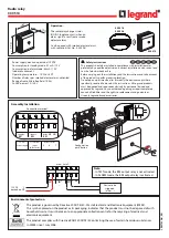
Rückführkreis
`
Feedback loop
`
boucle de retour
Rückführkreis/
feedback loop/
boucle de retour
Rückführkreis/feedback loop/ boucle de retour
`
Halbleiterausgang
`
Semiconductor output
`
Sortie statique
Betrieb
Das Gerät ist betriebsbereit, wenn die LED Po-
wer permanent leuchtet.
LEDs zeigen den Status und Fehler während
des Betriebs an:
LED leuchtet
LED blinkt
INFO
Statusanzeigen und Fehleranzeigen kön-
nen unabhängig voneinander auftreten. Bei
einer Fehleranzeige leuchtet oder blinkt die
LED "Fault" (Ausnahme: "Versorgungs-
spannung zu gering"). Eine zusätzlich blin-
kende LED weist auf eine mögliche
Fehlerursache hin. Eine zusätzlich statisch
leuchtende LED weist auf einen normalen
Betriebszustand hin. Es können mehrere
Statusanzeigen und Fehleranzeigen gleich-
zeitig auftreten.
Operation
The unit is ready for operation when the Power
LED is permanently lit.
LEDs indicate the status and errors during op-
eration:
LED on
LED flashes
INFORMATION
Status indicators and error indicators may
occur independently. In the case of an error
display, the "Fault" LED will light or flash
(exception: "Supply voltage too low"). An
LED that is also flashing indicates the po-
tential cause of the error. An LED that is lit
and is static indicates a normal operating
status. Several status indicators and error
indicators may occur simultaneously.
Utilisation
L'appareil est prêt à fonctionner lorsque la LED
Power reste allumée en permanence.
Les LEDs indiquent l'état et les erreurs lors du
fonctionnement:
LED allumée
LED clignotante
INFORMATION
L'affichage de l'état et des erreurs peut sur-
venir indépendamment. Lors de l'affichage
d'une erreur, la LED "Fault" s'allume ou cli-
gnote (exception : "Tension d'alimentation
trop faible"). Une LED clignotante supplé-
mentaire informe sur une cause possible
d'erreur. Une LED supplémentaire qui s'al-
lume de façon permanente informe de l'état
normal de fonctionnement. Plusieurs affi-
chages de l'état et des erreurs peuvent sur-
venir en même temps.
Statusanzeigen
Status indicators
Affichages d'état
Power
Versorgungsspannung liegt an.
Power
Supply voltage is present.
Power
la tension d'alimentation est présente.
In1
Taster an S11 ist betätigt.
In1
Pushbutton on S11 is operated.
In1
Le poussoir sur S11 est actionné.
In2
Taster an S21 ist betätigt.
In2
Pushbutton on S21 is operated.
In2
Le poussoir sur S21 est actionné.
Out
Sicherheitskontakte sind geschlossen und
Halbleiterausgang Y32 führt High-Signal.
Out
Safety contacts are closed and semicon-
ductor output Y32 carries a high signal.
Out
Les contacts de sécurité sont fermés et la
sortie statique Y32 délivre un niveau haut.
Reset
An S34 liegt 24 V DC an.
Reset
24 VDC is present at S34.
Réarmement
24 V DC sur S34.
Fehleranzeigen
Fault indicators
Affichage des erreurs
Alle LEDs aus
Diagnose: Querschluss/Erdschluss; Gerät
ausgeschaltet
`
Abhilfe: Querschluss/Erdschluss behe-
ben, Versorgungsspannung für 1 Min.
ausschalten.
All LEDs off
Diagnostics: Short across contacts/earth
fault; unit switched off
`
Remedy: Rectify short across contacts/
earth fault, switch off supply voltage for 1
min.
Toutes les LEDs sont éteintes
Diagnostic : court-circuit/mise à la terre ;
appareil éteint
`
Remède : supprimer le court-circuit/la
mise à la terre, couper la tension d'ali-
mentation pendant 1 min.
Fault
Diagnose: Abschlussstecker nicht gesteckt
`
Abhilfe: Abschlussstecker stecken, Ver-
sorgungsspannung aus- und wieder ein-
schalten.
Fault
Diagnostics: Plug terminator not connected
`
Remedy: Insert plug terminator, switch
supply voltage off and then on again.
Fault
Diagnostic : fiche de terminaison non bran-
chée
`
Remède : brancher la fiche de terminai-
son, couper puis remettre en marche la
tension d'alimentation
Fault
Diagnose: Interner Fehler, Gerät defekt
`
Abhilfe: Versorgungsspannung aus- und
wieder einschalten, gegebenenfalls Ge-
rät tauschen.
Fault
Diagnostics: Internal error, unit defective
`
Remedy: Switch supply voltage off and
then on again, change unit if necessary.
Fault
Diagnostic : erreur interne, appareil défec-
tueux
`
Remède : couper puis remettre en mar-
che la tension d'alimentation, si besoin
échanger l'appareil
Power
Diagnose: Versorgungsspannung zu gering
`
Abhilfe: Versorgungsspannung überprü-
fen.
Power
Diagnostics: Supply voltage too low
`
Remedy: Check the supply voltage.
Power
Diagnostic : tension d'alimentation trop fai-
ble
`
Remède : vérifier la tension d'alimenta-
tion
K5 K6
K5
L1
N
K6
S24
13 (23,33)
S34
14 (24,34)
S24
S34
Y32
PLC Input
S14
Gnd


