background image

OPERATING AND INSTALLATION INSTRUCTIONS LG 250 A 


     PAGE 49

U

S

ER

G

ENER

A

L

S

P

EC

IA

LIS

P

ER

S

O

NNEL

Changes reserved

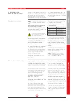
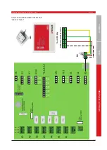
When connecting an external reheater 
battery, the supply air temperature sensor 
T4 installed in the ventilation unit must 
be connected to input T5 (outdoor air 
temperature). 

The external supply air sensor (available 
as an optional accessory), 5 m in length, is 
connected to input T5 and installed in the 
air duct after the heater battery. The user 

must switch to the "Re-heater battery" 
parameter in the operating software. 

If a temperature sensor is not connected 
to input T5, a fault message is output. 
Where the reheater battery is controlled 
using external temperature control, the 
reheater battery parameter in the operat-
ing software must be set to "None". 

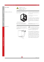
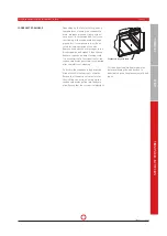
Connection for an electric reheater battery 

16. Maintenance and cleaning 

Always pull the mains plug or 
fully isolate the ventilation unit 
from the mains when carrying 

out cleaning or maintenance work on the 
ventilation unit! 

Other unit parts and components e.g. geo-
thermal heat exchanger, pre- and reheat-
er battery, sound absorbers etc. must be 
serviced and cleaned in accordance with 
the regulations and instructions. When 
opening or unscrewing the front cover or 
covers, always proceed with extreme care, 
with due attention to safety and risks.

If possible, use a vacuum cleaner to 

remove dirt and dust. Applying force or 
using compressed air for cleaning may 
damage components and surfaces.

Never use aggressive or solvent-contain-
ing cleaning agents. 

The electrical components must not be 
exposed to moisture or wet conditions. 

The 

Safety 

information under 

Section 4

- and in particular the 

point on electrical 

connections (Page 9)  -

 must be observed 

when performing any electrical work.

SAFETY INSTRUCTIONS

Only specialists are allowed to 
carry out the work specifi ed 
below on the ventilation unit. Any 

defects detected during servicing must 
be remedied immediately to ensure safe 
operation of the unit. 

Only original spare parts may be used for 
repairs and replacements.

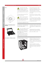
MAINTENANCE INSTRUCTIONS FOR SPE-

CIALIST COMPANIES

Attention:

 Bypass fl aps do not 

move or drive manually.

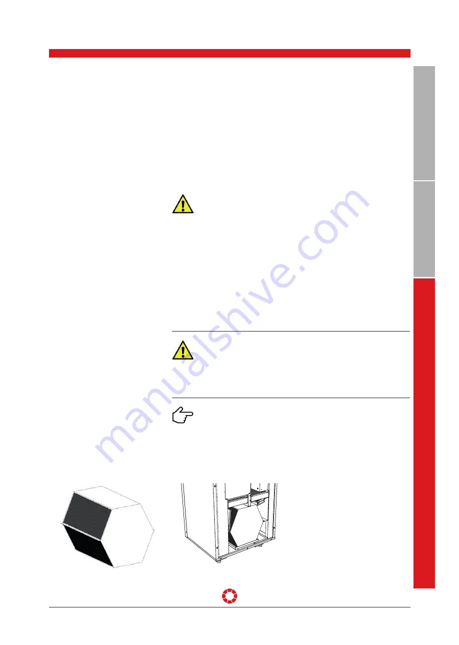
Annual cleaning is recommended at the 
least, depending on the degree of soiling 
of the heat exchanger.

The heat exchanger must be carefully 
removed from the unit for maintenance. 

The heat exchanger can be cleaned by 
rinsing with warm water (maximum 
50 °C) and normal detergents, and fi nally 
rinsing with warm water. Never blast the 
exchanger with compressed air. This can 
destroy the heat exchanger! 

Before installing the exchanger in the 
unit, the guide rails on the heat exchanger 
must be greased lightly to ensure easy 
and smooth insertion.

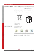
HEAT EXCHANGER WITH BYPASS FLAP 

A

1

2

3

C

E

1

D

2

3

B

7

A

E

IN

B

A

U

V

O

R

S

C

H

L

A

G

C

4

4

5

6

7

E

D

5

6

B

Benennung:

Datum:

Gezeichnet:

Kunde:
Blatt Nr.

Dateiname:

Maßstab:

DIESER PLANUNGSVORSCHLAG IST NUR IN VERBINDUNG MIT UNSEREN VORBEMERKUNGEN GÜLTIG!

BEHÖRDENAUFLAGEN SIND BAUSEITIG ABZUKLÄREN UND UNBEDINGT EINZUHALTEN!

NATURMASZE UND HÖHENKOTEN SIND ZU ÜBERPRÜFEN!

UNSTIMMIGKEITEN SIND MIT DEM PLANVERFASSER ABZUKLÄREN!

ALLE MASZE SIND VOR DER AUSFÜHRUNG VOM KUNDEN ZU PRÜFEN!

Geprüft:

Diese Zeichnung stellt

nach

den Urh. Ges § 24 unser geistiges Eigentum

dar und darf ohne unsere ausdrückliche Zustimmung weder Konkurrenzfirmen,

noch dritten Personen weitergegeben werden. Die unbefugte bzw. bestimmungswidrige

Verwendung dieser Unterlagen ist nicht gestattet und wird gerichtlich verfolgt.

08LG250-A-L-V LG250 Baugruppe

Gerät L

Baugruppe.idw

23.01.2017

wroth

Prüfer:

1 von 1
1 : 50

Freimaßtoleranz nach DIN ISO 2768-mH

Zeichnungsstatus: Freigegeben

Revision:

-

Gespeichert: 02.02.2017 14:05:13

Bauvorhaben:

Gewicht:

62,444 kg

Auftragsnummer:

J. Pichler Gesellschaft m.b.H
9021 Klagenfurt, Karlweg 5, Postfach 32

T +43 (0)46332769, F +43 (0)463 37548

[email protected], www.pichlerluft.at

wroth
30.11.2016

Zeichnungsnummer:

Artikelnummer.

08LG250-A-L-V

Summary of Contents for LG 250 A

Page 1: ...to local requirements and is valid up to the specified maximum air flow volume EU Regulation 1253 2014 2016 1254 2014 ENERGIA ENERGIJA ENERGY ENERGIE ENERGI LG 250 A A 43 dB 250 m h A A A A A A 80 A...

Page 2: ...ault notice messages Page 20 MINI CONTROL UNIT PAGE 20 TOUCH CONTROL UNIT PAGE 20 9 Filter maintenance Page 21 MAINTENANCE INSTRUCTIONS AIR FILTER PAGE 21 FILTER MESSAGE ON THE MINI CONTROL UNIT PAGE...

Page 3: ...ELECTRICAL WIRING DIAGRAM PAGE 45 ELECTRICAL WIRING DIAGRAM GATEWAY PAGE 46 CIRCUIT AND WIRING DIAGRAM CONTROL UNIT MINI OR TOUCH PAGE 47 MAINS CONNECTION PAGE 48 16 Maintenance and cleaning Page 49...

Page 4: ...e the right to modify our apparatus or technical data fully or in part and without prior notification The latest version of our General Terms and Conditions of Trade is applicable 1 Introduction Dear...

Page 5: ...es which are conducive to wear Any other use shall be deemed contrary to designated use The manufacturer shall accept no responsibility for damages or consequential damages arising from im proper use...

Page 6: ...air conditioning of buildings as amended must be taken into consideration when installing the air conditioning system in accordance with the instructions for fire protection Due to their heavy burden...

Page 7: ...al manufacturer supplied parts are installed or if unauthorised changes or modifica tions are made to the unit The warranty is voided automatically by failure to comply with the information in this in...

Page 8: ...y only be installed in compliance with national installation regulations Installation shall be carried out in ac cordance with the general local building safety and installation regulations of the rel...

Page 9: ...es that could compromise the unit s safety are prohibited To ensure safe operation safety devices must not be removed or bypassed Electrical equipment and the unit s warning and protective devices mus...

Page 10: ...chemicals Never operate the ventilation unit without an air filter Air filters must be checked regularly for dirt and damage and cleaned or replaced if necessary The air filters must be changed at le...

Page 11: ...compact ventilation unit comprises A compact non heat bridging and thermally insulated housing made from galvanised steel sheeting externally powder coated in RAL 9010 A high efficiency heat recovery...

Page 12: ...the unit switches to Standby mode or to Basic Ventilation operating mode A minimum volume flow of 30 m h is configured 7 LEDs The ventilation unit s various statuses are signalled via a total of 7 LED...

Page 13: ...ERATING MODE The active operating mode is displayed by various buttons The operating mode can be changed by pressing the buttons The following operating modes are available Summer Summer or bypass mod...

Page 14: ...t hand side change the unit s ventilation level Press ing the button increases the ventilation level until level III is reached which corre sponds to boost ventilation After 1 hour operating time in t...

Page 15: ...alue of 900 ppm is not exceeded Humidity concentration based control Figure2 The relative humidity is a factor that also contributes significantly to a comfortable living climate Acceptable humidity i...

Page 16: ...d to the Start menu by pressing the Home button Set the required temperature in stand ard mode Activate deactivate the time program Ambient air extract air or supply air is controlled depending on the...

Page 17: ...r control and display are displayed here as well as ventilation unit model and ventilator model Air volume Volume flow can be adjusted for each individual ventilation level here min and max volume flo...

Page 18: ...ddition three times can be specified for room temperature each day These times determine the time at which a particular ventilation level is activated Air filter changed If the air filter has been cha...

Page 19: ...eset controlled GL Basic Ventilation OFF Reset error Z04 Z05 Spezialist personnel The and options are displayed by pressing the No button The error is reset by selecting Yes and confirming with OK Err...

Page 20: ...perature sensor error The error LED flashes briefly three times in succession followed by a long pause General fault The error LED flashes briefly four times in succession followed by a long pause Com...

Page 21: ...f the specified quality class may be used 9 Filter maintenance 1 Filter ETA ISO Coarse 90 extract air optional filter ETA ISO ePM10 75 2 Filter ODA ISO ePM2 5 65 outdoor air optional filter ODA ISO eP...

Page 22: ...ere can I order filters Use only original replacement filters of the filter class specified FILTER CHANGING 1 Filter stentering rails 2 Air filter 1 2 3 1 2 3 7 A EINBAUVORSCHLAG C 4 4 5 6 7 E D 5 6 B...

Page 23: ...ing If the air filters are replaced prematurely the filter counter must be reset without a pending filter message Press the button and the button at the same time for 5 seconds in order to do this CLE...

Page 24: ...x H x D 672 x 870 x 610 mm Weight approx 65 kg with no optional accessories Ensure that the unit is not damaged from being toppled or overturned Avoid knocks and blows during transportation Applicabl...

Page 25: ...Y 2 x 2 x 0 8 shielded max length 100 m Air filter Outdoor air filter Filter ODA ISO ePM2 5 65 optional filter ODA ISO ePM1 80 Extract air filter Filter ETA ISO Coarse 90 optional filter ETA ISO ePM1...

Page 26: ...4 42 45 1000 Hz 32 36 40 30 33 37 55 62 66 54 56 59 24 31 36 2000 Hz 22 27 34 19 24 29 46 56 61 46 48 53 21 31 36 4000 Hz 15 17 25 12 17 22 39 49 55 39 42 48 17 28 33 8000 Hz 18 18 18 11 12 15 35 46 5...

Page 27: ...py exchanger 8 Condensate drain 9 Frost protection heater with PTC low temperature preheater battery optional 10 Bypass flap with servo motor 11 Supply air fan 12 Exhaust air fan 13 Front cover with h...

Page 28: ...the energy content from the extract air and transfers this to supply air Optional enthalpy exchanger available 8 Condensate drain Condensate generated during the operation of the heat exchanger is dir...

Page 29: ...or enthalpy exchanger for moisture recovery Version Left hand version Right hand version Item no without an integrat ed preheater battery 08LG250A L 08LG250A R Item no with an integrated preheater ba...

Page 30: ...xchanger 6 Exhaust air fan 7 Supply air fan 8 Control system 9 Bypass flap 10 Filter ETA ISO Coarse 90 extract air 11 Filter ODA ISO ePM2 5 65 outdoor air 12 Condensate tray 13 Cable inlet 4 x M16 1 x...

Page 31: ...particularly effective in air tight building shells and with active thermal insulation A temperature change rate of up to 84 7 heat recovery provides highly efficient energy savings It must in partic...

Page 32: ...systems are available to monitor defrosting of the heat exchanger Possible strategies to protect against freezing are outlined below SYSTEM ENHANCEMENT OPTIONS FOR FROST PROTECTION Optimal frost prote...

Page 33: ...hermal heat exchanger s parametered summer threshold value In this case the outdoor air is drawn in via the geothermal heat exchanger and is thus pre cooled If the outdoor temperature optional T5 sens...

Page 34: ...eater battery is connected cold outdoor air is pre heated via the integrated electrical PTC low temperature battery This operating mode provides guaranteed balanced air flow volume between supply air...

Page 35: ...ter batteries which can be integrated into the air ducting system Additional Heating mode is only available in Winter mode SYSTEM EXPANSION FOR ADDITIONAL INTERNAL HEATING With external electric air h...

Page 36: ...he menu for ventilation level I by pressing the Summer and buttons simultaneously for 3 seconds The volume flow is configured using the and buttons If no buttons are pressed for 5 seconds the paramete...

Page 37: ...word The Service menu is indicated with an S in the top left edge of the screen The technician can change the unit s parameters after activating the Service menu Change temperature control type The Co...

Page 38: ...ontrolled BV Off see page 19 Reset Error Z04 05 see page 19 Reset time meter Delete message overview Test mode Test the unit s basic func tions Update the system s firmware Test mode Test relays Test...

Page 39: ...cannot be moved The outdoor air and exhaust air ducts e g between the ventilation unit and the roof feed through must be sufficiently insu lated for energy reasons and to prevent condensate formation...

Page 40: ...nsate drainage The alignment of the unit is made easy thanks to the settable and adjustable unit feet Ensure adequate distance between floor and underside of the unit Installing the ventilation unit D...

Page 41: ...cht gestattet und wird gerichtlich verfolgt 08LG250 A L V LG250 Baugruppe Ger t L 08LG250 A L V LG250 Baugruppe Ger t L seite 45 idw 23 01 2017 WRoth Pr fer 1 von 1 1 10 Freima toleranz nach DIN ISO 2...

Page 42: ...AND COMPO NENTS 1 Supply air connection 160 mm 2 Extract air connection 160 mm 3 Outdoor air connection 160 4 Exhaust air connection 160 5 Cable inlets 4 x M16 1 x M12 1 2 3 4 3 1 4 1 2 3 4 3 1 4 2 SE...

Page 43: ...rning hazardous electrical voltage Disregarding the hazard may result in death injury or mate rial damage Before carrying out any work on live parts the unit must always be dis connected completely fr...

Page 44: ...T INSTALLATION The temperature sensor is located on the underside of the control unit To ensure accurate and conclusive temperature measure ment it is important to place the control unit in a location...

Page 45: ...RING DIAGRAM 1 2 3 N L 1 2 3 1 2 3 1 2 3 1 2 3 1 2 3 PE 1 2 3 1 1 M1 1 1 1 M s su A 1 s o o o o s u A A ss A A os d o s A A u A A 1 o o A A A o o s 1 A A 1 A A 1 1 1 D o o o d 1 d s 1 u o 1 D b u 1 o...

Page 46: ...GND 2 24VDC 1 1 2 3 1 2 3 4 1 2 1 2 3 4 1 2 3 4 U3 U4 1 2 T1 1 2 3 1 2 3 1 2 3 4 1 2 3 N L 1 2 3 1 2 3 1 2 3 1 2 3 1 2 3 PE 1 2 3 1 2 3 4 Relay Relay Relay Relay Relay Relay Relay FUSE2 Sicherung T4AH...

Page 47: ...ION INSTRUCTIONS LG 250 A PAGE 47 USER GENERAL SPECIALIST PERSONNEL Changes reserved Mini Touch Display B1 A B GND 24VDC 1 R ckseite Bedieneinheit A 1 B 2 GND 3 24VDC 4 CIRCUIT AND WIRING DIAGRAM CONT...

Page 48: ...the mains power supply ensures all pole disconnection of the unit from the power supply The ventilation unit may be op erated with the rated voltage of 230 V 50 Hz indicated on the nameplate only The...

Page 49: ...on unit Any defects detected during servicing must be remedied immediately to ensure safe operation of the unit Only original spare parts may be used for repairs and replacements MAINTENANCE INSTRUCTI...

Page 50: ...LE MASZE SIND VOR DER AUSF HRUNG VOM KUNDEN ZU PR FEN Gepr ft Diese Zeichnung stellt nach den Urh Ges 24 unser geistiges Eigentum dar und darf ohne unsere ausdr ckliche Zustimmung weder Konkurrenzfirm...

Page 51: ...C 4 4 5 6 7 E D 5 6 B Benennung Datum Gezeichnet Kunde Blatt Nr Dateiname Ma stab DIESER PLANUNGSVORSCHLAG IST NUR IN VERBINDUNG MIT UNSEREN VORBEMERKUNGEN G LTIG BEH RDENAUFLAGEN SIND BAUSEITIG ABZU...

Page 52: ...ERAL SPECIALIST PERSONNEL In order to document maintenance works this table must be completed after perfor mance of works on the unit SERVICE TABLE Unit installed by Date No Maintenance works e g filt...

Page 53: ...air vents inlet and outlet valves properly installed and open Are the air filters in the ventilation unit correctly installed and clean Are the air filters in the geothermal heat exchanger etc correc...

Page 54: ...xhaust air fan blocked Z05 Supply air fan blocked Z06 Short circuit temperature sensor T1 Z07 Short circuit temperature sensor T2 Z08 Short circuit temperature sensor T3 Z09 Short circuit temperature...

Page 55: ...low blow 10 A 5 x 20 mm 40LG040110 NTC thermistor sensor length 2 m 40LG041081 SYSTEM COMPONENTS Designation Item number Water reheater battery 08PWW250 3 way motorised mixing valve R3015 P63 S1 Tr230...

Page 56: ...nual eating sa e S aste isposal otor an ri e entilation control 2 m h W LWA dB A 50 Pa 0 W m h S x ilter c ange A Responsible for the content J Pichler Gesellschaft m b H Photos Archiv J Pichler Gesel...

Page 57: ...sumption nnual eating sa e S aste isposal otor an ri e entilation control 2 m h W LWA dB A 50 Pa 0 2 W m h S x ilter c ange A Responsible for the content J Pichler Gesellschaft m b H Photos Archiv J P...

Page 58: ...related products Die Konformit t mit den Richtlinien wird nachgewiesen durch die Einhaltung folgender Normen und Verordnungen Conformity to the Directives is assured through the application of the fol...

Page 59: ...OPERATING AND INSTALLATION INSTRUCTIONS LG 250 A PAGE 59 USER GENERAL SPECIALIST PERSONNEL Changes reserved Note...

Page 60: ...ichler Gesellschaft m b H Photos Ferdinand Neum ller Archiv J Pichler Gesellschaft m b H Text J Pichler Gesellschaft m b H All rights reserved All images are for reference only Subject to amendment Ve...

Reviews: