OPERATING AND INSTALLATION INSTRUCTIONS LG 250 A
PAGE 43
U
S
ER
G
ENER
A
L
S
P
EC
IA
LIS
T
P
ER
S
O
NNEL
Changes reserved
15. Electrical connection
PROCEDURE
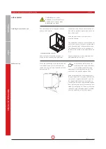
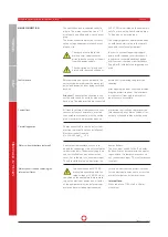
1. Open the unit
When opening the ventilation unit to per-
form electrical connections, the wing nuts
will need to be released and the access
doors opened.
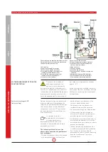
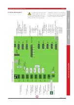
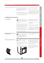
2. Controller circuit board
The control circuit board is located on the
left upper half of the unit. The protective
sheeting must be removed to access to
the terminal slots.
Attention!:
The protective sheeting is con-
nected with the unit’s earth by means of a
flush plug. The plug must be disconnected
before finally removing the protective
sheeting.
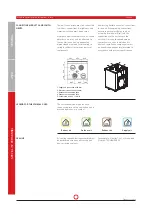
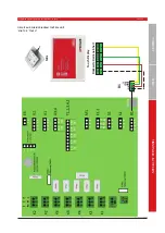
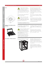
3. Cable feed-throughs
Connection cables must be fed through
the cable glad on the top of the ventilation
unit in order to connect the cables for the
relevant control unit as well as optional
system components such as external
reheating or external sensors.
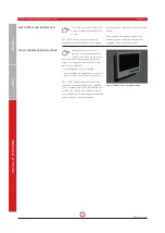
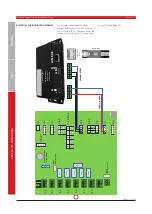
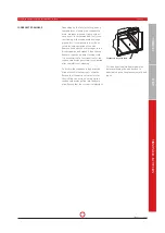
4. Connecting the control unit to the
control panel
The control system consists of a control
panel and a control unit. The control panel
is connected to the control unit using a
bus connection. The control panel can
communicate internal statuses and op-
erating and fault messages to the control
unit via this line connection.
A screened cable Y(ST) J-Y(ST)Y2x2x0.8 is
required to establish the connection.
Cable length must not exceed 100 m.
The screening must be connected to the
ventilation unit’s PE protective earthing.
The connecting cable is included in the
scope of supply.
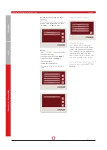
The connection to the control circuit board
and “MINI” operating unit is achieved with
a socket, and with a threaded connection
for the “TOUCH” operating unit.
• Warning: hazardous electrical
voltage!
• Disregarding the hazard may
result in death, injury or mate-
rial damage.
• Before carrying out any work on live
parts, the unit must always be dis-
connected completely from the power
supply (all poles) and secured against
being switched back on!
Electrical connection and work on electri-
cal components may only be carried out
by authorised electricians only.
The relevant national and local regula-
tions and standards must be complied
with during assembly and electrical
installation.
The LG 250 A compact ventilation unit is
designed for a 230 V/50 Hz power supply.
The unit is not designed for connection to
three-phase supply with 400 V/50 Hz.
The safety information under Item 4 -
and, in particular, the point on electrical
connections – must be observed when
performing any electrical work.
• Electrics must be connected in accord-
ance with the associated wiring plan.
(see page 45)!
• The cable cross-sections indicated are
minimum cross-sections for copper
lines and do not take cable length or site
conditions into account.
• Cable type, cable cross-section and lay-
ing must be determined by an author-
ised electrician!
• Low-voltage cables must be laid sepa-
rately from mains cables; alternatively,
screened cables must be used!
• The inlet fuse on the power supply line
must be an isolation type!
• A separate cable inlet must be used for
each cable!
• Unused cable inlets must be hermetical-
ly sealed!
• All cable entries must be strain-relieved!
• Potential equalisation must be put in
place between the unit and the air duct
system!
• All safety measures must be tested
following electrical connection! (Earth
resistance etc.)
• In order to prevent triggering inappro-
priate earth-leakage circuit breakers, it
is expressly recommended that pulsed
or all-current-sensitive circuit breakers
(Type A or B) with delayed triggering are
used.


