OPERATING AND INSTALLATION INSTRUCTIONS LG 250 A
PAGE 39
U
S
ER
G
ENER
A
L
S
P
EC
IA
LIS
T
P
ER
S
O
NNEL
Changes reserved
The LG 250 A compact ventilation unit
must be installed in accordance with the
general and locally applicable safety and
installation regulations and as per the
specifications in this Manual. Mounting
and installation work may be performed
by authorised specialist personnel only.
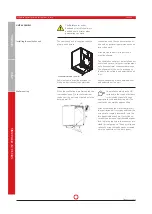
The ventilation unit may only be installed
in a frost-free room, e.g. in a cellar or
loft, with ambient temperatures ranging
b5°C to +40°C. Accumulating
condensate water must be discharged,
frost-free and safely, via a gradient and
using effective siphoning to block odours.
The unit's installation position must allow
sufficient space for air ducts, electrical
connections, condensate drain connection
and maintenance and inspection.
Leave at least 1 m free space in front
of the unit to allow for operation and
servicing.
The ventilation unit must be set up on
an even and sufficiently firm installation
surface. The ventilation unit can also be
secured to a solid wall using the wall
assembly bracket included in the scope
of delivery. Care must be taken to ensure
the appropriate design of the (Static)
load-bearing components when doing so.
The following connection facilities must
be available in the installation area:
• Air duct connections for supply, extract,
outdoor and exhaust air
• Electrical mains connection 230 V/
50 Hz, 16 A fuse
• Condensate drain line with eff ective
odour trap (siphon)
All on-site work (drainage, floor structure
etc.) must be completed before installing
the ventilation unit. The ventilation unit
will be firmly in position once the air
ducts have been connected and cannot be
moved.
The outdoor air and exhaust air ducts, e.g.
between the ventilation unit and the roof
feed-through, must be sufficiently insu-
lated for energy reasons and to prevent
condensate formation.
Condensate must not be allowed to form
on the air ducts and roofing. Any lines
running outdoor the thermally insulated
building shell must be adequately insulat-
ed in cold areas.
To ensure proper and functional operation
of the unit, suitable thermal and sound
insulation and installation materials must
be provided as per the planning documen-
tation and technical data, such as sound
absorbers of adequate size, supply air and
extract air valves, overflow openings etc.
All equipment connectors should in
principle be fitted with sound absorbers
to ensure appropriate acoustic damping in
the living area.
Air duct feed-throughs through walls or
ceilings must be isolated against structur-
al vibrations.
To protect the unit from coarse soling
such as foliage, leaves or insects, a fine
wire mesh grating must be provided as a
pre-filter directly at the central inlet point
for outdoor air. The protective grating
must be checked and cleaned at regular
intervals, if necessary, especially in spring
and autumn.
Inspection openings should be provided in
the air duct system to facilitate cleaning
as well as maintenance of the unit.
14. Installation
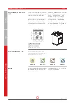
PREREQUISITES FOR UNIT INSTALLA-
TION
1
2
3
4
3
1
4
2
1
2
3
4
3
1
4
2
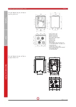
544
484
672
332
92
77
8
633
610
16
16
87
0
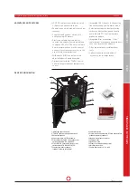
1 Zu
luft ø 160 mm
2 Abluft
ø 160 mm
3 Außenluft
ø 160 mm
4 Fortluft
ø 160 mm
5 Gegenstromwärmetauscher
6 Abluftventilator
7 Zuluftventilator
8 Steuerung
9 Bypassklappe
10 Abluftfilter G4
11 Außenluftfilter F7
12 Kondensatwanne
13 Kabeleinführung 4 x M16 / 1 x M12
14 PTC-Elektrovorheizregister (optional)
15 Höhenverstellbare Füße
16 Kondensatstutzen
Abbildung:
LG 250 A-L (linke Ausführung)
Aufbauskizze (Stand- oder Wandmontage, linke Ausführung)

