OPERATING AND INSTALLATION INSTRUCTIONS LG 250 A
PAGE 40
Changes reserved
U
S
ER
G
ENER
A
L
S
P
EC
IA
LIS
T
P
ER
S
O
NNEL
The
Safety
notes under
Section 4
of this Manual must
be heeded at all times when
performing any work!
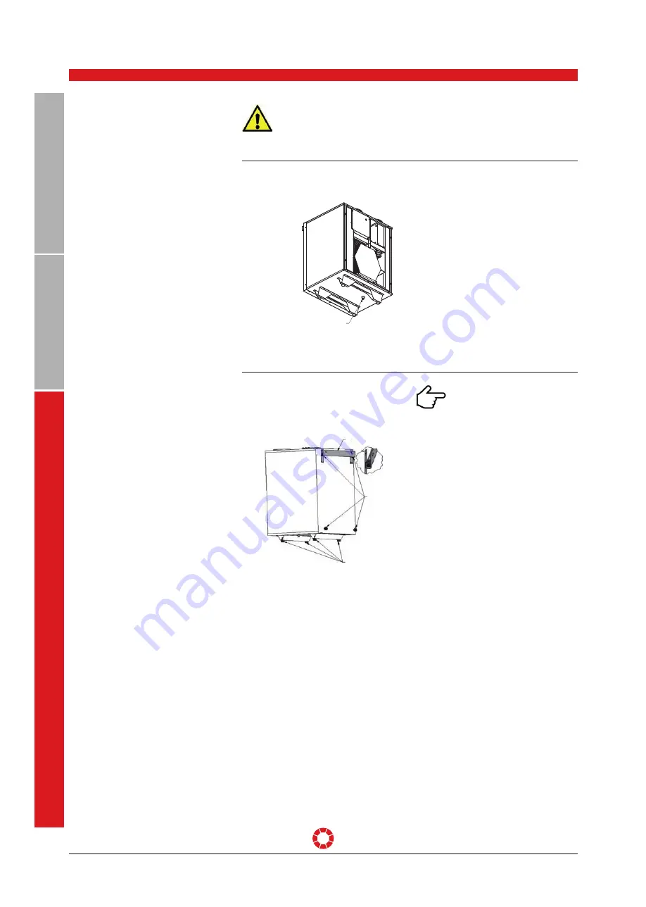
UNIT ASSEMBLY
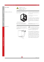
When the ventilation is wall-mounted, the
four rubber pads (1) are removed from
the base of the unit and screwed onto the
backing wall (2).
The wall assembly bracket (3)
included in the scope of delivery
is installed horizontally on an
appropriate solid load-bearing wall. The
ventilation unit weighs approx. 65 kg.
After assembling the wall assembly rail,
the ventilation unit is suspended from the
using wall assembly bracket (3) with the
two upper rubber buff ers. It must be en-
sured when doing so that the rubber pads
lock in place properly in the recesses pro-
vided for that purpose. The unit is aligned
vertically using the rubber pads screwed
onto the underside of the back panel.
Wall mounting
The ventilation unit is supplied ready to
plug in and operate.
Suffi
cient space must be provided for
fi tting air duct connections, electrical
connections and the condensate connec-
tion and for performing maintenance and
inspection work.
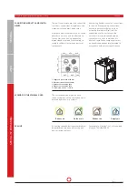
After placing the unit in its position, it
must be aligned.
The ventilation unit must be installed hori-
zontal and secure. Only precise alignment
will ensure optimal condensate drainage.
The alignment of the unit is made easy
thanks to the settable and adjustable unit
feet.
Ensure adequate distance between fl oor
and underside of the unit.
Installing the ventilation unit
Detail A ( 1 : 5 )
A
A
1
2
3
C
E
1
D
2
3
B
7
A
E
IN
B
A
U
V
O
R
S
C
H
L
A
G
C
4
4
5
6
7
E
D
5
6
B
Benennung:
Datum:
Gezeichnet:
Kunde:
Blatt Nr.
Dateiname:
Maßstab:
DIESER PLANUNGSVORSCHLAG IST NUR IN VERBINDUNG MIT UNSEREN VORBEMERKUNGEN GÜLTIG!
BEHÖRDENAUFLAGEN SIND BAUSEITIG ABZUKLÄREN UND UNBEDINGT EINZUHALTEN!
NATURMASZE UND HÖHENKOTEN SIND ZU ÜBERPRÜFEN!
UNSTIMMIGKEITEN SIND MIT DEM PLANVERFASSER ABZUKLÄREN!
ALLE MASZE SIND VOR DER AUSFÜHRUNG VOM KUNDEN ZU PRÜFEN!
Geprüft:
Diese Zeichnung stellt
nach
den Urh. Ges § 24 unser geistiges Eigentum
dar und darf ohne unsere ausdrückliche Zustimmung weder Konkurrenzfirmen,
noch dritten Personen weitergegeben werden. Die unbefugte bzw. bestimmungswidrige
Verwendung dieser Unterlagen ist nicht gestattet und wird gerichtlich verfolgt.
08LG250-A-L-V LG250 Baugruppe
Gerät L
08LG250-A-L-V LG250 Baugruppe Gerät L seite 45.idw
23.01.2017
WRoth
Prüfer:
1 von 1
1 : 10
Freimaßtoleranz nach DIN ISO 2768-mH
Zeichnungsstatus: Freigegeben
Revision:
-
Gespeichert: 10.04.2017 09:25:42
Bauvorhaben:
Gewicht:
62,446 kg
Auftragsnummer:
J. Pichler Gesellschaft m.b.H
9021 Klagenfurt, Karlweg 5, Postfach 32
T +43 (0)46332769, F +43 (0)463 37548
[email protected], www.pichlerluft.at
wroth
30.11.2016
Zeichnungsnummer:
Artikelnummer.
08LG250-A-L-V
Kondensatanschluss
15 mm
Kondensattasse mit Abluss
Condensate drain ø 16,5 mm
2
1
3

