OPERATING AND INSTALLATION INSTRUCTIONS LG 250 A
PAGE 48
Changes reserved
U
S
ER
G
ENER
A
L
S
P
EC
IA
LIS
T
P
ER
S
O
NNEL
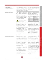
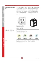
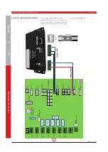
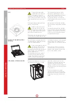
An external temperature sensor is re-
quired for connection of an external water
re-heater battery. The external supply air
sensor (available as an optional acces-
sory), 2 m in length, is connected to input
T5 and installed in the air duct after the
heater battery.
The user must switch to the "Re-heater
Battery - Water" parameter in the operat-
ing software. If a temperature sensor is
not connected to input T5, a fault message
is output.
Water re-heater battery (external)
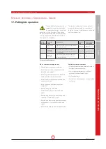
The ventilation unit LG 250 A
may only be operated with the
rated voltage of 230 V/50 Hz as
specified on the nameplate. Before work-
ing on the electrical power unit, all poles
of the equipment must be isolated from
mains and protected against renewed
switch-on. Unscrew the protective cover
for the electrical power unit to access the
mains terminals and electrical fuses.
Internal fuse:
Glass tube fuse, T10A H ø 5 x 20 mm ,
slow-blow.
Mains connection and replacing the
internal unit fuses
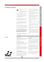
The ventilation unit is supplied ready to
plug in. The mains connection line is 1.5
m in length and fitted with a shock-proof
plug.
The mains connection must be correctly
set up using an appropriate shock-proof
plug on site.
The shock-proof plug in the
mains power supply ensures
all-pole disconnection of the unit
from the power supply.
The ventilation unit may be op-
erated with the rated voltage of
230 V / 50 Hz indicated on the nameplate
only. The fuse on the line should be max.
16 A and be an isolating type.
The supply pipe must be dimensioned by
an authorised electrician in full compli-
ance with the relevant guidelines.
In order to prevent triggering inappro-
priate earth-leakage circuit breakers, it
is expressly recommended that pulsed
or all-current-sensitive circuit breakers
(Type A or B) with delayed triggering are
used.
MAINS CONNECTION
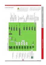
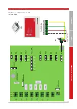
All lines for external components such as
sensors, actuators, pumps etc. must be
connected in accordance with the wiring
plan. Lines must be dimensioned by an
electrician. Low-voltage cables must be
laid separately from mains cables; alter-
natively, screened cables must be used.
Control lines
Pumps connected to the control system
must be intrinsically safe and stallproof.
Electrical connection with
U = 230 VAC and I
max
= 2 A
Circulating pumps
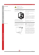
Before working on the control board, the
unit must be isolated from the mains (all
poles) and protected from being switched
back on.
Attention!:
The protective sheeting is con-
nected with the unit's earth by means of a
flush plug. The plug must be disconnected
before finally removing the protective
sheeting.
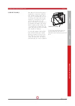
After opening the front cover and disman-
tling the protective panel, the terminals
for the control lines and the electrical
input fuse are accessible.
Control board


