Physik Instrumente E-625.C0 User Manual Download Page 1


Physik Instrumente (PI) GmbH & Co. KG, Auf der Roemerstrasse 1, 76228 Karlsruhe, Germany 
Phone +49 721 4846-0, Fax +49 721 4846-1019, Email [email protected], www.pi.ws 


PZ166E 

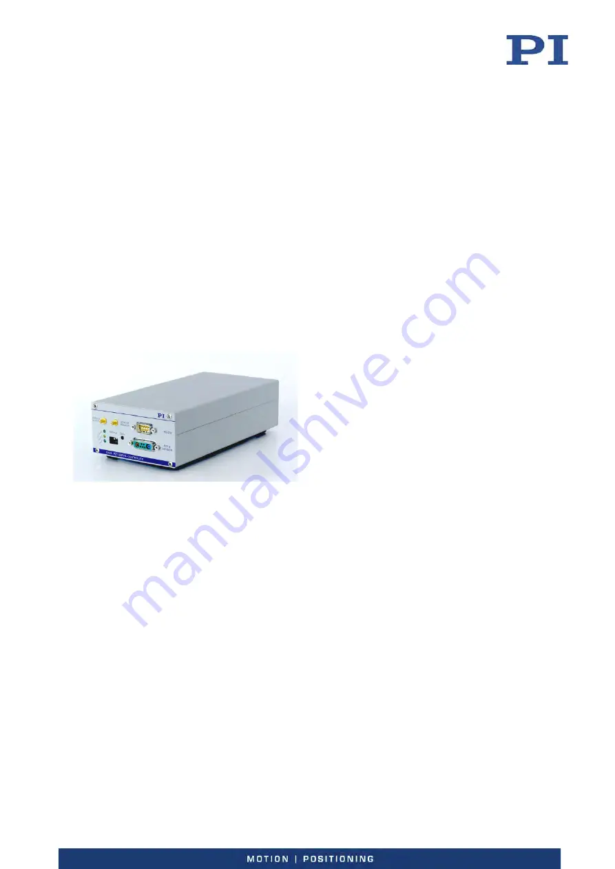
E-625 Piezo Servo Controller 

User Manual 

Version: 2.0.0 


Date: 15.09.2021 


This document describes the following products: 


E-625.CR


Piezo servo controller, single channel, for 

capacitive sensors 


E-625.C0


Piezo servo controller, single channel, for 

capacitive sensors, only analog control 


Summary of Contents for E-625.C0

Page 1: ... 1019 Email info pi ws www pi ws PZ166E E 625 Piezo Servo Controller User Manual Version 2 0 0 Date 15 09 2021 This document describes the following products E 625 CR Piezo servo controller single channel for capacitive sensors E 625 C0 Piezo servo controller single channel for capacitive sensors only analog control ...

Page 2: ...ente PI GmbH Co KG Karlsruhe Germany The text photographs and drawings in this manual are protected by copyright Physik Instrumente PI GmbH Co KG reserves all rights in this respect The use of any text images and drawings is permitted only in part and only when indicating the source Original instructions First printing 15 09 2021 Document number PZ166E BRo Version 2 0 0 Subject to change This manu...

Page 3: ...3 3 2 Rear Panel 11 3 4 Scope of Delivery 12 3 5 Accessories 12 4 Unpacking 13 5 Installation 15 5 1 General Notes on Installing 15 5 2 Ensuring Ventilation 15 5 3 Connecting the E 625 to the Protective Earth Conductor 15 5 4 Connecting the Power Supply to the E 625 16 5 5 Connect a Positioner to the E 625 17 5 6 Connecting a Signal Source to the E 625 18 5 7 Connecting a Measuring Device to E 625...

Page 4: ...3 3 Potentiometers 41 8 3 4 E 802 Servo Controller Submodule 41 8 4 Synchronizing the Sensors 41 8 5 Adjusting Notch Filter and P I Controller 43 8 5 1 Adjusting the Notch Filter 43 8 5 2 Setting the P I Controller in Analog Mode 46 8 6 Calibrating the Displacement of the Positioner 47 8 6 1 Adjusting the Sensor Range 48 8 6 2 Adjusting the Static Sensor Gain for Closed Loop Operation 51 8 6 3 Adj...

Page 5: ...12 4 1 E 625 CR Block Diagram 70 12 4 2 E 625 C0 Block Diagram 71 12 5 Pin Assignment 72 12 5 1 PZT SENSOR 72 12 5 2 Network 72 12 5 3 E 625 CN Network Cable 73 12 5 4 Power Supply Connector 73 13 Old Equipment Disposal 75 14 Appendix 77 14 1 Lifetime of PICMA Actuators 77 14 2 European Declarations of Conformity 81 ...

Page 6: ......

Page 7: ...g of basic servo systems as well as motion control concepts and applicable safety procedures The latest versions of the user manuals are available for download p 3 on our website 1 2 Symbols and Typographic Conventions The following symbols and typographic conventions are used in this user manual DANGER Immediate threat of danger Failure to comply could lead to death or serious injury Precautionar...

Page 8: ...ustrations may also differ and must not be seen as guaranteed properties 1 4 Other Applicable Documents The devices and software tools from PI mentioned in this documentation are described in separate manuals You can download all manuals mentioned hereafter in a zip file from our website To download the manuals use the E 816 and PI software links in the A000T0081 Downloading Manuals from PI pdf fi...

Page 9: ...ct our customer service department p 63 Downloading Manuals 1 Open the website www pi ws 2 Search the website for the product number e g P 882 or the product family e g PICMA bender 3 Click the corresponding product to open the product detail page 4 Click the Downloads tab The manuals are shown under Documentation Software manuals are shown under General Software Documentation 5 Click the desired ...

Page 10: ......

Page 11: ... for static as well as dynamic applications Capacitive sensors must be used for closed loop operation PI positioners intended for closed loop operation already have the corresponding sensors Other sensors can only be used with PI approval 2 2 General Safety Instructions The E 625 is built according to state of the art technology and recognized safety standards Improper use can result in personal i...

Page 12: ...y or death from electric shock Only open the E 625 housing when you are authorized and have the corresponding qualifications Before opening the housing disconnect the E 625 from the power source by removing the power plug When operating with an open housing do not touch any components in the housing aside from the adjustment elements described in this user manual 2 3 Organizational Measures User M...

Page 13: ...is equipped with an E 816 computer interface submodule This enables it to offer the following additional functions Multi axis network Several E 625 CR can be controlled from one single interface A special network cable sets up the communication between the individual controllers Waveform memory The user can save any function values in an internal table and output these with a trigger This makes it...

Page 14: ...rolled mode network operation of several devices E 625 C0 Piezo servo controller single channel for capacitive sensors only analog mode no network operation 3 3 Product View 3 3 1 Front Panel Figure 1 E 625 CR front panel ANALOG IN WTT SMB socket coaxial input line grounded on the line conductor The use depends on the control mode which is set up with the Settings DIP switch block see below ...

Page 15: ...V max frequency 400 Hz min pulse width 200 μs Refer to the user manual for the E 816 computer interface submodule SENSOR MONITOR SMB socket coaxial output line with grounded line conductor and 0 to 10 V on the inner conductor Filtered and converted sensor output value with 0 to 10 V for the nominal travel range The output impedance is 10 kΩ RS 232 only E 625 CR D sub panel plug 9 pole male for the...

Page 16: ... open loop operation E 625 CR only On the E 816 computer interface submodule the servo mode can be switched on with the SVO command 4 ON down Signal on ANALOG IN WTT used as the trigger for the wave table output or triggered motion OFF up Signal on ANALOG IN WTT not used as the trigger for the wave table output or triggered motion The switches 1 2 and 4 determine the control mode for the E 625 and...

Page 17: ...k connection only E 625 CR I2 C bus the synchronization of the sensor and the on target signal from the E 802 servo controller submodule The on target signal shows that the distance from the target position is less than 0 19 of the travel range The signal TTL active low is also applied to the On Target LED on the front panel of the E 625 Protective earth connector The protective earth connector th...

Page 18: ...r 3763 Power cord E 692 SMB SMB BNC adapter cable 1 5 m 2 pcs PZ300EK Short Instructions for Housed Analog Piezo Electronics PZ150E User manual for the E 802 servo controller submodule Only with E 625 CR C 815 34 Null modem cable for the connection to the PC 000036360 USB cable USB A m USB Mini B m for the connection to the PC PZ116E User manual for the E 816 computer interface submodule C 990 CD1...

Page 19: ...he contents with the scope of delivery according to the contract and the delivery note 3 Inspect the contents for signs of damage If any parts are damaged or missing contact our customer service department p 63 immediately 4 Keep all packaging materials in case the product needs to be returned 4 Unpacking ...

Page 20: ......

Page 21: ...y disconnected from the mains Only use cables and connectors that meet local safety regulations 5 2 Ensuring Ventilation High temperatures can overheat the E 625 Set up the E 625 with a distance of at least 10 cm to the top and rear sides and at least 5 cm to the sides If this is not possible make sure that the area is cooled sufficiently Ensure sufficient ventilation at the place of installation ...

Page 22: ...ck washer Nut Flat washer Lock washer Nut Suitable wrench Connecting the E 625 to the Protective Earth Conductor 1 If necessary attach a suitable cable lug to the protective earth conductor 2 Remove the outer nut from the protective earth connector on the rear panel of the E 625 threaded bolt p 11 marked with 3 Connect the protective earth conductor a Push the cable lug of the protective earth con...

Page 23: ...aft connector f to the E 625 s DC IN 12 30 V Switchcraft panel plug 2 Connect the adapter s barrel connector to the power supply s barrel connector socket 3 Connect the power cord to the power supply 5 5 Connect a Positioner to the E 625 Requirements The E 625 is switched off i e the wide range input power supply is not connected to the power socket over the power cord Tools and Accessories The po...

Page 24: ...in pulse width 200 μs SMB BNC adapter cable included in the scope of delivery Connecting a Signal Source Use the adapter cable to connect a suitable signal source to the ANALOG IN WTT SMB socket 5 7 Connecting a Measuring Device to E 625 INFORMATION The filtered and converted sensor output value with 0 to 10 V for the nominal travel range is on the SENSOR MONITOR SMB socket The signal is directly ...

Page 25: ...rolled mode p 32 the target value is given among other things by motion commands sent from the PC to the E 625 CR via the RS 232 or USB interface These commands are processed by the E 816 computer interface submodule on the E 625 CSR INFORMATION Several devices can be networked together and commanded from one single RS 232 or USB interface on the PC E 625 SR or E 665 piezo servo controllers can al...

Page 26: ...N The capacity of the I2 C bus is 400 pF The larger the number of devices to be interlinked the shorter the lines between the devices have to be The maximum length of the bus must not exceed 1 m When you use E 625 CN network cables you can interlink a maximum of 4 devices If you need to interlink more than 4 devices use the E 621 piezo servo controller modules from PI Up to 12 of these modules can...

Page 27: ...cessory p 12 Alternatively Suitable connection cables with the same pin assignment as the E 625 CN p 73 Networking the Controllers Figure 4 Interlinking via E 625 CN network cable Connect the Network sockets on the rear panels of the housings using the E 625 CN cables see figure or other suitable connection cables Networking can be done in a series or as a star The E 625 CN cables have D sub speci...

Page 28: ......

Page 29: ... earth conductor p 15 before starting Do not remove the protective earth conductor during operation If the protective earth conductor has to be removed temporarily e g in the case of modifications reconnect the E 625 to the protective earth conductor before restarting NOTICE Damage of the positioner from oscillations Oscillation of the positioner is indicated by humming and this is caused by incor...

Page 30: ... not require a function generator or a voltmeter You can then use the wave table output to generate a square wave signal to determine the resonant frequency and the settling behavior of the positioner and read out the position and output voltage via query commands For more information refer to the user manual for the E 816 computer interface submodule Requirements You have read and understood the ...

Page 31: ...the function generator d On the oscilloscope Y t or FFT diagram read the resonant frequency of the positioner If the resonant frequency is not dampened sufficiently peak too high e Open the E 625 p 36 f Adjust p 43 the notch filter accordingly on the E 802 servo controller submodule 4 Determine the position of the positioner at 0 V input voltage a Remove the oscilloscope from the SENSOR MONITOR SM...

Page 32: ...802 55 servo controller submodule p 43 7 Determine the settling behavior of the positioner in closed loop operation a Make sure that servo mode is switched on switch 3 on the Settings DIP switch block to ON down b Generate a 1 V square wave signal peak peak with 2 to 5 Hz using the function generator c On the oscilloscope observe the step response of the positioner sensor monitor signal over time ...

Page 33: ...t the Sensor Zero Point Changes in temperature or changes in the mechanical load can cause small deviations of the sensor zero point Objectives of the zero point adjustment Make the entire travel range available When the sensor zero point is set correctly the complete output voltage range of the amplifier can be used in closed loop operation Prevent the piezo actuators from damage In open loop ope...

Page 34: ...tmeter p 18 necessary in analog mode not necessary but helpful in computer controlled mode only E 625 CR If the voltmeter is used an additional SMB BNC adapter cable is necessary included in the scope of delivery Trimmer adjustment tool Performing the Zero Point Adjustment in Analog Mode 1 Select analog mode and open loop operation servo mode OFF using the Settings DIP switch block 1 ON down 2 OFF...

Page 35: ...ove 5 Send the SVO A 0 command A indicates the axis to ensure that servo mode is switched off 6 Increase the piezo voltage using the SVA command in increments of 10 volts from 0 V up to the value where the upper travel range limit for the positioner is reached approximately 7 Send the SVA A 0 command to set the piezo voltage to 0 V A indicates the axis 8 Read the sensor signal Use the voltmeter on...

Page 36: ...o Controller INFORMATION To prevent an overflow in open loop operation Do not exceed the recommended input voltage range of 2 to 12 V analog mode Do not command any piezo voltage outside of the recommended range of 20 to 120 V computer controlled mode ...

Page 37: ...5 to a protective earth conductor p 15 before starting Do not remove the protective earth conductor during operation If the protective earth conductor has to be removed temporarily e g in the case of modifications reconnect the E 625 to the protective earth conductor before restarting NOTICE Damage to the piezo ceramic The constant application of high voltage to the piezo actuators in the position...

Page 38: ...see the file Analog_Readme txt in the installation directory C ProgramData PI LabVIEW Computer Controlled Mode only E 625 CR The E 816 computer interface submodule that is integrated into the E 625 CR controls the generation of the piezo voltage The target value position or piezo voltage depending on the servo mode can be set by commands sent from the PC or from a running macro Furthermore the mot...

Page 39: ...hanges in load Open Loop Operation Control input signals input signal on ANALOG IN WTT or E 816 inputs over commands and wave table output are interpreted as a direct specification for the piezo voltage In open loop operation the servo loop for the E 802 servo controller submodule is not considered When the jumpers are set accordingly the slew rate limiter and the notch filter remain active p 38 T...

Page 40: ...625 CR and E 625 C0 Move the DIP switch 3 on the front panel of the E 625 to the corresponding position Servo mode Setting Switch setting Closed loop operation ON down Open loop operation OFF up SVO Command E 625 CR only INFORMATION To be able to set the servo mode over the E 816 computer interface submodule with the SVO command the DIP switch 3 must be set to open loop operation up Send the corre...

Page 41: ...hen you are authorized and have the corresponding qualifications Before opening the housing disconnect the E 625 from the power source by removing the power plug When operating with an open housing do not touch any components in the housing aside from the adjustment elements described in this user manual NOTICE Damage to the E 625 from electrostatics The E 625 contains electrostatic sensitive devi...

Page 42: ...using Notch filter and P I controller for optimal settling behavior p 43 Sensor settings for the highest positioning accuracy after the replacement of the positioner or the controller p 47 Master slave setting for the sensor synchronization p 41 8 2 Opening the Housing Only the Settings DIP switch block and the Zero potentiometer can be accessed from the outside All other E 625 adjustment elements...

Page 43: ... figure shows the position of the components and adjustment elements jumpers switches on the main board of the E 625 CR and on the E 802 55 servo controller submodule The servo controller submodule is inserted vertically on the main board The components of the E 625 C0 are identical except for the E 816 computer interface submodule The adjustment elements are shown in the default position ...

Page 44: ...oller submodule is activated default settings The servo mode can be controlled with switch 3 on the Settings DIP switch block and only for E 625 CR over the E 816 computer interface submodule The slew rate limiter for the piezo voltage and the notch filter remain active even when servo mode is switched off 2 3 The E 802 servo controller submodule is bypassed independent of all other settings The s...

Page 45: ...1 to JP106 The jumpers JP101 to JP106 are used to adjust the sensor range The figure below shows the jumper layout on the main board p 37 Figure 7 Settings for the sensor range jumpers The extension factors are set according to in the connected positioners If the positioner is not known to PI the extension factor of 1 0 is set Jumper JP107 to JP109 The jumpers JP107 to JP109 shift the voltage rang...

Page 46: ...2 55 servo controller submodule are described in the E 802 servo controller submodule user manual Master Slave Switch for the Sensor Synchronization In systems with several capacitive sensors the master slave switch makes the master slave settings The master slave switch is located on the printed circuit board which is soldered vertically on the main board see the circle in the following figure ne...

Page 47: ...le is explained in detail in a separate user manual 8 4 Synchronizing the Sensors The sensors can be synchronized in systems with several capacitive sensors For this the master slave switch configures one system as the sensor master The other systems are set as slaves Switch in master position default settings The excitation frequency of the sensors is provided internally Switch in slave position ...

Page 48: ...er adjustment tool or alternatively a narrow slot screwdriver Synchronizing the Sensors Figure 10 Settings for the master slave switch 1 Select an E 625 as the sensor master and check the position of the master slave switch The master position see top figure is the default setting 2 If the master slave switch on the selected sensor master is not in the master position use the trimmer adjustment to...

Page 49: ...er on the main board is in the default setting p 38 the notch filter and the slew rate limiter for the piezo voltage will be active when servo mode is switched off Readjusting the notch filter frequency in open loop operation could lead to a change in the piezo voltage up to 5 INFORMATION If you make the settings in the computer controlled mode you will not require a function generator You can the...

Page 50: ...not know the resonant frequency for the positioner determine it as follows a Set the notch filter frequency range as high as possible using the DIP switch block on the E 802 55 servo controller submodule all DIP switches to OFF b Generate a 1 V square wave signal peak peak with 2 to 5 Hz using the function generator c Read the resonant frequency and its level on the oscilloscope Y t or FFT display...

Page 51: ... the resonant frequency of the positioner has the best damping 12 Improve the settings of the P I controller p 46 In the two figures below you can find examples for resonant frequency measurements with a digital storage oscilloscope They show the input voltage and the sensor signal as well as the FFT Fast Fourier Transform of the sensor signal Figure 11 Open loop operation notch filter not adjuste...

Page 52: ... potentiometer on the E 802 55 servo controller submodule with the trimmer adjustment tool fully counterclockwise Typically you will hear a click c Switch the servo mode on again 2 Generate a 5 V square wave signal peak peak with 5 to 10 Hz using the function generator 3 On the oscilloscope observe the step response of the positioner sensor monitor signal over time 4 Alternatingly turn P2 and P3 I...

Page 53: ...g of P term and I term stable system with relatively long settling time 8 6 Calibrating the Displacement of the Positioner A recalibration of the displacement is only necessary when the positioner or parts of it or the E 625 of a calibrated system was replaced A calibrated external measuring device is used to recalibrate the position sensor back to the accuracy specified in the original measuremen...

Page 54: ...l positioners ordered together with a E 625 are delivered with measurement protocols as evidence of the system performance INFORMATION The calibration of the displacement of the positioner applies only to the control mode analog or computer controlled mode in which the settings were made In the other control modes you must expect a deviation of 1 With E 625 models that can be operated computer con...

Page 55: ...e High precision analog signal source p 18 SMB BNC adapter cable included in the scope of delivery Only in computer controlled mode PC with RS 232 or USB interface for commanding and installed software from the PI software CD High precision voltmeter p 18 necessary in analog mode not necessary but helpful in computer controlled mode only E 625 CR If the voltmeter is used an additional SMB BNC adap...

Page 56: ... Adjust the R143 p 37 sensor gain potentiometer on the main board with the trimmer adjustment tool until the until the voltage on the SENSOR MONITOR SMB socket is 10 V 12 If necessary repeat the last steps until stable values are displayed on the measuring devices Do you want to use your system in closed loop operation If so For the highest positioning accuracy in closed loop operation adjust p 51...

Page 57: ...djustment tool until the sensor shows the nominal displacement The voltmeter on the SENSOR MONITOR SMB socket shows 10 V or The response to the POS A command shows the upper travel range limit in µm 14 If necessary repeat the last steps until stable values are displayed on the measuring devices Do you want to use your system in closed loop operation If so For the highest positioning accuracy in cl...

Page 58: ...l range limit 6 If the sensor signal on the SENSOR MONITOR SMB socket deviates from 10 0000 V Adjust the GAIN fine adjust potentiometer P6 on the E 802 55 servo controller submodule using the trimmer adjustment tool until the sensor signal is exactly 10 0000 V refer to the E 802 user manual 7 If the measurement value on the external measuring device deviates from the upper travel range limit Adjus...

Page 59: ...on the SENSOR MONITOR SMB socket is not 10 0000 V Adjust the GAIN fine adjust potentiometer P6 on the E 802 55 servo controller submodule using the trimmer adjustment tool until the sensor signal corresponds exactly to the upper travel range limit refer to the E 802 user manual 7 Read the measured value on the external measuring device The value must correspond exactly to the upper travel range li...

Page 60: ...ive direction of motion Increase the input voltage on the ANALOG IN WTT SMB socket in increments of 1 volt from 0 V to 10 V and read the position of the positioner from the external measuring device For the linearization of the negative direction of motion Reduce the input voltage stepwise from 10 V to 0 V 2 Using the trimmer adjustment tool adjust the R144 p 37 ILS adjust potentiometer on the mai...

Page 61: ...socket 5 Close the E 625 8 6 4 Digital Corrections only E 625 CR In addition to the adjustments described in this user manual the E 816 computer interface submodule can be used to digitally correct the following values Value Unit Function Sensor coefficient Ks μm V When the sensor signal changes by 1 V the position changes by Κs μm Sensor offset Os μm When the sensor signal is 0 V the position is ...

Page 62: ......

Page 63: ...he housing Before cleaning disconnect the E 625 from the power source by removing the mains plug Prevent cleaning fluid from penetrating the housing When necessary clean the surfaces of the E 625 s housing using a cloth dampened with a mild cleanser or disinfectant 9 2 Updating Firmware The E 625 CR module is equipped with an E 816 computer interface submodule whose firmware can be updated For upd...

Page 64: ......

Page 65: ... source used for the axis motion E 625 CR only In the analog mode motion commands from the computer interface or from running macros trigger input and wave table output are ignored and can provoke an error message Remember the priority of the individual control sources refer to the user manual for the E 816 computer interface submodule The input voltage is not present or exceeds the permissible ra...

Page 66: ...requency and or the amplitude and or the output duration Communica tion with the controller fails The wrong communication cable is used or it is defective Check the cable The RS 232 connection requires a null modem cable Check whether the cable works on a fault free system Communication interface is not configured correctly When using the RS 232 interface Check the port settings and the baud rate ...

Page 67: ... starting work While the E 625 is not in use Make sure that servo mode is switched off open loop operation and the piezo voltage is set to 0 V Analog mode The input voltage for the target value is 0 V Computer controlled mode Corresponding commanding The positioner starts oscillating or positions inaccurately The load was changed Readjust the system according to the changed load p 35 Overflow LED ...

Page 68: ...ation of driver routines Vis Check whether the system works with a terminal program If so Read the information in the corresponding software manual and compare the sample code on the PI software CD with your program code If the problem that occurred with your system is not listed in the table above or cannot be solved as described contact our customer service department p 63 ...

Page 69: ... information Product and serial numbers of all products in the system Firmware version of the controller if applicable Version of the driver or the software if applicable Operating system on the PC if applicable If possible Take photographs or make videos of your system that can be sent to our customer service department if requested The latest versions of the user manuals are available for downlo...

Page 70: ......

Page 71: ...https www pi ws 12 1 Specifications 12 1 1 Data Table E 625 CR E 625 C0 Function Piezo amplifier servo controller Channels 1 Sensor E 625 CR E 625 C0 Controller type P I analog notch filter Sensor type capacitive Amplifier E 625 CR E 625 C0 Input voltage range 2 to 12 V Min output voltage 30 to 130 V Peak current 50 ms 120 mA Average output current 60 mA Current limitation Short circuit proof Nois...

Page 72: ... libraries for Windows DLL and Linux Supported functions Wave table 256 data points external trigger up to 16 macros Miscellaneous E 625 CR E 625 C0 Operating temperature range 5 to 50 C Overheat protection Deactivation at 75 C Dimensions 205 mm 105 mm 60 mm Mass 1 05 kg Operating voltage 12 to 30 V DC stabilized included in the scope of delivery external power adapter Current consumption 2 A E 62...

Page 73: ...a of application For indoor use only Maximum altitude 2000 m Air pressure 1100 hPa to 0 1 hPa Relative humidity Highest relative humidity 80 for temperatures up to 31 C Decreasing linearly to 50 relative air humidity at 40 C Storage temperature 0 C to 70 C Transport temperature 25 C to 85 C Overvoltage category II Protection class I Degree of pollution 2 Degree of protection according to IEC 60529...

Page 74: ... 0 0 PZ166E E 625 Piezo Servo Controller 12 2 Operating Limits The following diagram shows the operating limits in open loop operation for various piezo loads The curve values are capacitance values in μF Figure 15 Operating limits ...

Page 75: ...12 Technical Data E 625 Piezo Servo Controller PZ166E Version 2 0 0 69 12 3 Dimensions Figure 16 E 625 dimensions in mm ...

Page 76: ... 1 E 625 CR Block Diagram Figure 17 E 625 CR block diagram S1 sw 4 S1 sw 1 S1 sw 2 and S1 sw 3 refer to the switches 4 1 2 and 3 on the Settings DIP switch block on the E 625 front panel The pin numbers 2a to 32c refer to an internal 32 pin connection and are only used for informational purposes ...

Page 77: ...0 Block Diagram Figure 18 E 625 C0 block diagram S1 sw 4 S1 sw 1 S1 sw 2 and S1 sw 3 refer to the switches 4 1 2 and 3 on the Settings DIP switch block on the E 625 front panel The pin numbers 2a to 32c refer to an internal 32 pin connection and are only used for informational purposes ...

Page 78: ... D socket 9 pole female Pin Function 1 GND 2 GND 3 SCL I2 C network operation not for E 625 C0 4 SDA I2 C network operation not for E 625 C0 5 GND 6 On target signal TTL active low Shows that the distance from the target position is less than 0 19 of the travel range 7 100 kHz sensor synchronization 8 3 2 MHz sensor synchronization 9 Not connected The SCL and SDA bus connections are limited to a m...

Page 79: ... PZ166E Version 2 0 0 73 12 5 3 E 625 CN Network Cable Figure 19 Pin assignment of E 625 CN network cable 12 5 4 Power Supply Connector Switchcraft panel plug 3 pole male Pin Function 1 GND 2 12 to 30 VDC 15 V recommended stabilized 3 Not connected ...

Page 80: ......

Page 81: ...nternational national and local rules and regulations In order to fulfil its responsibility as the product manufacturer Physik Instrumente PI GmbH Co KG undertakes environmentally correct disposal of all old PI equipment made available on the market after 13 August 2005 without charge Any old PI equipment can be sent free of charge to the following address Physik Instrumente PI GmbH Co KG Auf der ...

Page 82: ......

Page 83: ...etime of PICMA Actuators The lifetime of a PICMA piezo actuator can be influenced by the following factors Applied voltage Temperature Relative humidity The following diagrams show how the individual factors influence the lifetime of the actuator Figure 20 Dependency of the mean time between failure MTTF of a PICMA actuator on the applied voltage 14 Appendix ...

Page 84: ...E 625 Piezo Servo Controller Figure 21 Dependency of the mean time between failure MTTF of a PICMA actuator on the ambient temperature Figure 22 Dependency of the mean time between failure MTTF of a PICMA actuator on the relative humidity ...

Page 85: ...ponentially with decreasing voltage The recommended maximum range for the input voltage of the E 625 is therefore 2 to 12 V This results in a piezo voltage range of 20 to 120 V in open loop operation The input voltage range can be expanded from 3 to 13 V the piezo voltage is then in the range of 30 to 130 V which however reduces the lifetime of the actuator Example see markings in the diagrams App...

Page 86: ......

Page 87: ...y For the E 625 declarations of conformity were issued according to the following European statutory requirements Low Voltage Directive EMC Directive RoHS Directive The standards applied for certifying conformity are listed below Safety Low Voltage Directive EN IEC 61010 1 EMC EN 61326 1 RoHS EN IEC 63000 ...

Reviews: