


Nanoline
58
PHOENIX CONTACT
2338_en_O
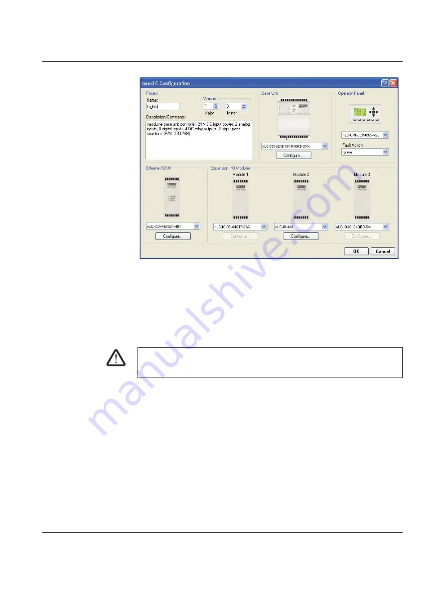
Figure 4-2
nanoNavigator 3 “Nanoline Configuration” dialog box showing
configuration of NLC-055… system
•
Ensure correct selection of the base unit and I/O expansion modules in each drop-down
menu.
The inputs should be turned on at their physical location (one at a time) and checked within
nanoNavigator to assure proper setup and operation.
4.1.4.4
Addressing the outputs
Before checking the output channels, ensure the Nanoline is stopped. From the Operator
Panel:
•
Press the <Shift> and <OK> keys on the Operator Panel.
•
Press the <1> key to stop processing.
Or from nanoNavigator:
•
Click the “nanoLC… Stop nanoLC!” menu to stop processing.
•
Click the “nanoLC… Disconnect” menu to release the connection to the Nanoline.
The physical location of each output (where the wires will be connected) must be verified to
ensure the physical output is associated with the correct software address. If channels are
not available, check the project configuration in nanoNavigator to ensure proper base unit
and expansion module selections (see Figure 4-2).
•
Click the “nanoLC… Configuration” menu to open the “nanoLC Configuration” dialog
box.
•
Ensure correct selection of the base unit and I/O expansion modules in each drop-down
menu.
WARNING:
Ensure all personnel are clear of controlled devices. Outputs that are inadvertently
energized can cause sudden movement of connected devices.
Summary of Contents for Nanoline NLC-035-024D-04I-02QRD-05A
Page 1: ...User manual Installing and using Nanoline controllers UM EN NLC...
Page 8: ...Nanoline 4 PHOENIX CONTACT 2338_en_O...
Page 38: ...Nanoline 34 PHOENIX CONTACT 2338_en_O...
Page 54: ...Nanoline 50 PHOENIX CONTACT 2338_en_O...
Page 66: ...Nanoline 62 PHOENIX CONTACT 2338_en_O...
Page 94: ...Nanoline 90 PHOENIX CONTACT 2338_en_O...


