


Status 14.07.09
We reserve the right to make
changes favouring technical
progress.
Operating Instructions
thermos 200 / 300 DC
with automatic control unit
®
WÄRMERÜCKGEWINNUNG
© Paul Wärmerückgewinnung GmbH • August-Horch-Straße 7 • 08141 Reinsdorf • Deutschland
Tel: +49(0)375-303505-0 • Fax: +49(0)375-303505-55 • E-Mail: [email protected] • Internet: www.paul-lueftung.de
3
2.2
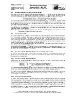
Motorised valve for ground to air heat exchanger
If a ground to air heat exchanger (GHX) is installed upstream of the MVHR unit on the intake side, a
motorised valve offers the option to take in the outdoor air either via the GHX or directly. Depending on the
outdoor temperatures (separate sensor required), the valve is set to air intake via GHX e.g. as follows;
Air intake via GHX at t
intake
> 25°C (cooling in summer operation)
Air intake via GHX at t
intake
< 5°C (pre-heating in winter operation)
The air is taken in directly (not via GHX) for all other temperatures (t
intake
= 5°C to 25°C). The temperature
sensor shall be placed close to the second intake point for recording the outdoor air temperature without
being heated by the sun. The sensor is included in deliveries with the control unit option “Motorised valve
for ground to air heat exchanger”.
The bypass has to be enabled, activated and parameterised (see User Guidance of Automatic Control
Unit, Section 2.3). The customer is responsible for connecting the valve to the power supply according to
the circuit diagram in Appendix 4.3.
Note:
When a ground to air heat exchanger is used, this valve is not indispensable. The permanent current
consumption of the valve motor is about 50mA.
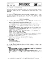
2.3
Constant flow control
The balance between the supply and extract air flows is crucial for proper operation of the MVHR system.
This flow balance is normally established by adjusting the fan power (ventilation step) and the correction
value. In constant flow control, analogue flow sensors are used to measure the two air flows, which are
then balanced by the constant flow mechanism. The advantage of constant flow control is that it adapts to
changing conditions and is independent of ventilation steps. Neither do fan motor irregularities (motor
winding, internal electronics) have an impact on the flow balance.
The constant flow control needs 2 analogue flow sensors to be integrated in straight tubes of the same
diameter (see Appendix 3.3 and Appendix 4.5).
When setting the parameters, it is possible to store a flow disbalance. The constant flow control has to be
activated and parameterised via the control unit in the menu System setup – ventilation steps (see User
Guidance of Automatic Control Unit, Section 2.5).
2.4
Ground to brine to air frost protection / electric frost protection heater
A ground to air heat exchanger / ground to brine to air frost protection, or a temperature-controlled frost
protection pre-heater should be used to prevent ice formation on the exhaust side of the heat exchanger.
Frost protection is indispensable.
2.4.1
Ground to brine to air frost protection
Depending on the outdoor temperature (separate sensor required), the pump of the ground to brine to air
frost protection is set as follows:
Pump ON:
at t
intake
< 0°C (pre-heating in winter operation)
Pump ON:
at t
intake
> 25°C (cooling in summer operation)
Pump OFF:
at t
intake
= 5°C to 25°C (no pre-heating of intake air)
The temperature sensor shall be placed close to the second intake point for recording the outdoor air
temperature without being heated by the sun. The sensor is included in deliveries with the control unit
option “Ground to brine to air frost protection / Motorised valve for ground to air heat exchanger”.
The pump has to be enabled, activated and parameterised (see User Guidance of Automatic Control Unit,
Section 2.3). The customer is responsible for connecting the pump to the power supply according to the
circuit diagram in Appendix 4.3a.
2.4.2
Electric frost protection heater
To ensure frost protection, the air in the extract-exhaust section of the heat changer shall never fall below
the freezing point. If frost protection is provided by the electric pre-heater from PAUL, it will adapt
automatically to the changing conditions of the intake and exhaust air. The temperature of the exhaust air
is permanently recorded and evaluated. If the temperature of the exhaust air falls below 2°C, the intake air
will be pre-heated for so long until the exhaust air temperature exceeds 2°C again. This ensures optimum
energy supply and prevents the condensate from freezing. The installation of the frost protection heater is
described in Appendix 4.6. The heater with ohmic heating element shall be installed according to Appendix
4.6.a and the ISO heater with PTC heating element according to Appendix 4.6.b.
Summary of Contents for thermos 200
Page 2: ......
Page 46: ......
Page 47: ......
Page 48: ......
Page 52: ......
Page 53: ......
Page 54: ......
Page 55: ......
Page 56: ......
Page 57: ......
Page 58: ......
Page 59: ......
Page 60: ......
Page 61: ......
Page 62: ......
Page 63: ......
Page 64: ......
Page 65: ......
Page 66: ......


