


Status 14.07.09
We reserve the right to make
changes favouring technical
progress.
Technical Description
Automatic Control
thermos 200 / 300 DC
© Paul Wärmerückgewinnung GmbH • August-Horch-Straße 7 • 08141 Reinsdorf • Deutschland
Tel: +49(0)375-303505-0 • Fax: +49(0)375-303505-55 • E-Mail: [email protected] • Internet: www.paul-lueftung.de
1
1. Introduction
The mechanical ventilation control unit is a modular microcontroller system. The following modules are available for
building customised systems: switched-mode power pack, controller board, switch module and programmer (operator
controls).
All controlling and regulating tasks of the mechanical ventilation control unit are organised by the main controller board
(HCE). The configuration program is designed such that all parameters can be configured via the programmer.
A five-button programmer with display is provided for convenient operator access. If required, you can connect several
displays in series.
A switched-mode power pack (PP) supplies the electricity to the ventilation fans and control unit.
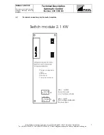
The control system can be extended by 2 switch modules for controlling 230 VAC terminals or loads.
Due to the modular construction of the control system, it is possible to set up simple as well as complex control
configurations covering all PAUL mechanical ventilation control variants.
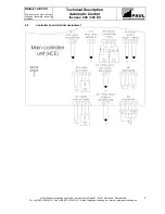
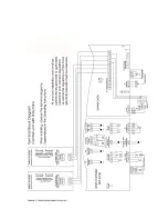
The photograph shows a fully equipped control unit.
2. Main Controller Unit (HCE)
The HCE uses a microcontroller PIC 16 C67 having a clock frequency of 20 MHz. Analogue input variables are
evaluated by one, or in other variants, two AD converters with 8 analogue channels (each).
A switched-mode power pack supplies electricity to the HCE and all modules.
A 20-pos. connector (ST_UB) between the power pack and the controller board supplies 12 VDC and 24 VDC to the
HCE.
Up to 8 modules can be connected for 230 VAC ventilation equipment. The modules are operated and supplied with
the operating voltages (12/24 VDC) by the HCE via the internal 34-pos. bus connector (ST_BUS).
All sensors and bypass motors are connected to the HCE.
The connected sensors are checked and evaluated according to the enabled functions or modules. Once a module or a
function is enabled, a hardware detection and sensor plausibility check is performed before the program is actually run.
If an error is found, the programmer display shows the error log and the relevant program part is not executed.
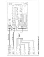
switch modules (option for frost prot.
back-up heater or heating
circuit)
power board
main controller unit (HCE)
voltage distribution (230V)
mains feeder
Summary of Contents for thermos 200
Page 2: ......
Page 46: ......
Page 47: ......
Page 48: ......
Page 52: ......
Page 53: ......
Page 54: ......
Page 55: ......
Page 56: ......
Page 57: ......
Page 58: ......
Page 59: ......
Page 60: ......
Page 61: ......
Page 62: ......
Page 63: ......
Page 64: ......
Page 65: ......
Page 66: ......


