


Status 14.07.09
We reserve the right to make
changes favouring technical
progress.
Technical Description
Automatic Control
thermos 200 / 300 DC
© Paul Wärmerückgewinnung GmbH • August-Horch-Straße 7 • 08141 Reinsdorf • Deutschland
Tel: +49(0)375-303505-0 • Fax: +49(0)375-303505-55 • E-Mail: [email protected] • Internet: www.paul-lueftung.de
3
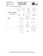
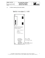
2.1
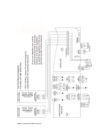
HCE Basis Version
The basis version is equipped only with one 8-channel AD converter and the associated terminals.
In connection with external components or associated modules, the basis version can realise the following functions or
operating modes:
•
Summer/winter bypass operation
•
Frost protection pre-heater (additional switch module required)
•
Air duct heater (additional switch module required)
•
Constant
flow
control
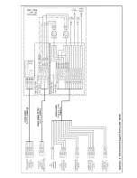
Connector pin assignment:
Plug X3-1
T1
(NTC temp. sensor for intake air at inlet of MVHR)
Plug X3-2
Frost protection safety sensors
(STB, flow sensor)
Plug X4
External programmer
Plug X7-1
T5
(NTC temperature sensor for duct heater / heating circuit – duct temperature or flow temperature)
Plug X7-2
(Electric) back-up heater safety sensors
(STB, flow sensor)
If a hot water duct heater or water-based heating circuit is used, there is no STB and no flow sensor.
Plug X8
Bypass
(summer/winter bypass)
Plug X11 T2
(NTC temp. sensor outdoor)
Plug X13
Flow sensors
(Fz2 - supply air, Fz3 - extract air)
Required for constant flow control only!
Plug X14
T3
(NTC temperature sensor f. supply air),
T4
(NTC temp. sensor f. extract air)
Summary of Contents for thermos 200
Page 2: ......
Page 46: ......
Page 47: ......
Page 48: ......
Page 52: ......
Page 53: ......
Page 54: ......
Page 55: ......
Page 56: ......
Page 57: ......
Page 58: ......
Page 59: ......
Page 60: ......
Page 61: ......
Page 62: ......
Page 63: ......
Page 64: ......
Page 65: ......
Page 66: ......


