


Status 14.07.09
We reserve the right to make
changes favouring technical
progress.
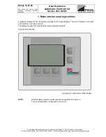
Operating Instructions
thermos 200 / 300 DC
with automatic control unit
®
WÄRMERÜCKGEWINNUNG
© Paul Wärmerückgewinnung GmbH • August-Horch-Straße 7 • 08141 Reinsdorf • Deutschland
Tel: +49(0)375-303505-0 • Fax: +49(0)375-303505-55 • E-Mail: [email protected] • Internet: www.paul-lueftung.de
8
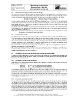
6. Care and maintenance by service staff
(see check list B)
According to DIN 1946/6 Chapter 6, the inspection and service interval is 2 years and includes the
following operations:
Filter check or change (see above) and cleaning of heat exchanger (HX). Cleaning is performed according
to level of contamination and maintenance interval every 2 years (important for 5-year warranty for the heat
exchanger).
Procedure:
1. Disconnect the MVHR unit from the power supply (de-energise).
2. Remove all assembly clips from the MVHR unit – remove air ducts from MVHR where necessary
3. Take off the top section of the heat exchanger box
4. Remove the heat exchanger box from the fan box by pulling it gently upwards and to the side.
5. Wash the heat exchanger by pouring warm water (< 50°C) with washing-up liquid through the two
air openings, turn the heat exchanger and repeat the washing process, then allow excess to drip
off.
6. In case of calcification, spray vinegar solution from the air inlet side onto the heat exchanger
surfaces in 3 applications 20 minutes apart, and then rinse with water in the end.
7. Check the condensate drain and clean, if required
8. Fill condensate trap with water
9. Re-assemble the MVHR unit in reverse order (Make sure the bypass shut-off insert points to the
front).
10. Re-connect the MVHR unit with the power supply (re-energise)
General inspection of the MVHR unit:
1. Contamination
2. Electrical safety
3. Leaktightness of condensate connection
The supply and extract air passages (valves) should be cleaned in this context.
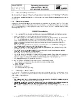
7. Control unit
7.1 Operator
comfort
Standard functions
•
8 independent time programs can be defined by the user and assigned to any day of the week
•
motorised summer bypass valve
•
manual stop in standby mode with limited power input below 2 W
•
manual adjustment of ventilation steps (off, minimum, normal, maximum)
•
programmer can be installed in any place in the house
•
ventilation steps programmable in 1% increments (30-100% of maximum fan power)
•
adjustable balance between supply and extract air fans
•
filter monitor for change interval
•
Freeze protection for downstream hot water duct heater
Options
(with extra price for accessories)
•
Control of an electric valve at the ground to air heat exchanger (either air intake through the ground to
air heat exchanger or direct air intake)
•
Control of a frost protection pre-heater (frost protection heater prevents ice formation and thus replaces
a ground to air heat exchanger in winter)
•
Constant flow control (permanent monitoring and balancing of the supply and extract air flows)
•
and thus compliant with fireplaces
•
Control of a heating circuit (e.g. heating circuit pump or electric back-up duct heater up to 2.1 kW) –
also with night reduction
•
Several boost switches can be connected to the programmer.
The MVHR unit can be operated by several programmers (e.g. in the place of installation, another one
in the living room). If a duct heater is used, the room temperature is recorded at the first programmer.
Note:
The description of the control menus can be found in the “User Guidance Automatic
Control Unit thermos 200 / 300 DC”.
Summary of Contents for thermos 200
Page 2: ......
Page 46: ......
Page 47: ......
Page 48: ......
Page 52: ......
Page 53: ......
Page 54: ......
Page 55: ......
Page 56: ......
Page 57: ......
Page 58: ......
Page 59: ......
Page 60: ......
Page 61: ......
Page 62: ......
Page 63: ......
Page 64: ......
Page 65: ......
Page 66: ......


