background image

Installation and servicing manual

Air Oil Coolers, LHC


14

Parker Hannifin Corporation

Hydraulics Group

Catalogue HY10-6004-UM/EU

Preventive maintenance/Maintenance

Preventive maintenance

Preventive maintenance work must be carried out at regular 

intervals. Make sure:

• that there is no abnormal noise or vibrations,

• that the air oil cooler is securely fixed,

•  that the cooler matrix is clean as debris will reduce the cooling 

capacity,

•  that  the  fluid  cleanliness  is  as  recommended,  replace  if 

required,

•  that the air oil cooler is free from damage, replace damaged 

components,

•  that  the  air  oil  cooler  is  free  from  leaks,  take  appropriate 

measures,

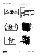
•  that  warning  labels  are  in  good  condition,  replace  any 

damaged/missing label immediatelyly.

Cleaning
 

 Caution

 Risk of bodily injury. Prior to cleaning, disconnect 

all motor power supplies.


 Caution

 Risk of severe burns. The air oil cooler could 

become extremely hot during operation. Make sure the air 

oil cooler is cool before touching.

Air oil cooler

 When cleaning the exterior of the cooler, for in-

stance using water, disconnect all power supplies. Be aware of 

the electric motor protection standard.

Cooler matrix

 The air fins of the matrix can be cleaned 

by blowing through with compressed air. If necessary a 

highpressure washing system and degreasing agent can be 

used. When using a high-pressure washing system point the 

jet parallel to the air fins. 

See Figure 6.

Fan housing

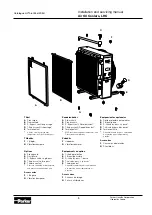
 Remove the cooler matrix when cleaning the 

inside of the fan housing. To clean the inside of the fan housing, 

use compressed air. If necessary a degreasing agent can be 

used. Blow with compressed air from the electric motor side 

through the fan guard.

Maintenance

Olear shall not be held responsible for any consequences due to 

repair and/or modification made by the customer.

Dismounting the cooler matrix
 

 Caution

 Risk of severe burns. The air oil cooler could 

become extremely hot during operation. Make sure the air 

oil cooler is cool before touching.


 Caution

 Risk of bodily injury. Disconnect the motor power 

supply prior to maintenance.

1. Turn off the system.

2. Disconnect the electric motor power supply.

3. Make sure that the system is depressurized.

4. Disconnect the oil inlets and outlets.

5. Disconnect the flexible hydraulic hoses from the cooler matrix.

6.  Unscrew the screws with washers fixing the cooler matrix to 

the fan housing. 

See Figure 7.

7. Remove the cooler matrix.

Mounting of the cooler matrix

1. Locate the cooler matrix.

2. Fit the cooler matrix to the fan housing. 

See Figure 7.

3.  Connect the flexible hydraulic hoses to the cooler matrix. 

See Figure 4

4. Connect the electric motor power supply

5. Proceed to 

Prior to start-up and At start-up.

Removing the electric motor and the fan
 

 Caution

 Risk of severe burns. The air oil cooler could 

become extremely hot during operation. Make sure the air 

oil cooler is cool before touching.


 Caution

 Risk of bodily harm. Prior to maintenance, 

disconnect the electric motor power supply.

Important

 Risk of damage to the hydraulic system. Contamination, 

water and air will increase wear on hydraulic components, which 

could lead to breakdown. The most important practice to observe 

when working on the hydraulic system is cleanliness.

Note!

 Some fan hubs are fixed, 

see Figure 194

, and some 

are detachable, 

see Figure 10 A and Figure 10 B.

 The fan is 

balanced together with the hub as from size LAC-033.

1. Turn off the system.
2. Disconnect the electric motor power supply.
3. Secure the electric motor.
4.  Unscrew the screws with washer fixing the motor 

attachment to the fan housing, 

see Figure 8

.

5.  Unscrew the screw with washer fixing the fan to the motor 

shaft. 

See Figure 9

. Pull with care the fan and hub from the 

motor shaft. Use a pulley if required.

6.  Unscrew the screws fixing the motor to the motor attach-

ment. 

See Figure 11.

7. Remove the motor.

If further dismounting of the fan is required, label all details to 
ensure correct mounting, first of all with regard to balance and 
direction of rotation. 

See Figure 12.

Mounting of the electric motor and fan
Note! 

There are models with fixed hub (

see Figure 9

) and models 

with detachable hub (

see Figure 10 A and Figure 10 B

). The fan is 

balanced together with the hub as from size LHC-033.
1.  Secure the hydraulic motor to the motor attachment. 

See Figure 11.

2.  Fit the hub groove to the motor spline. Lube the hub 

with ethanol and secure the fan/hub to the motor shaft. 

If required, knock carefully with e.g. a rubber mallet. Use 

Loctite® on the screw and secure the fan/hub on the motor 

shaft with screws.

 See Figure 9.

3.  Make sure that the fan is fitted to the motor shaft without too 

much play.

4  Place the motor attachment with fan, fan guard and motor in 

the fan housing.

5.  Adjust the fan guard and motor and secure the motor 

attachment in the fan housing with screws. 

See Figure 8.

6.  Make sure that the fan is centered and rotates freely (using 

hand force). If required, adjust the location of the fan guard 

and motor.

7. Check the screws for tightness.

8. Connect the hydraulic motor power supply.

9. Proceed to Prior to start-up and At start-up..

Summary of Contents for LHC

Page 1: ...HC with Hydraulic Motor for Mobile and Industrial Use Installation and servicing manual aerospace climate control electromechanical filtration fluid gas handling hydraulics pneumatics process control...

Page 2: ...manual Air Oil Coolers LHC 2 Parker Hannifin Corporation Hydraulics Group Catalogue HY10 6004 UM EU Catalogue HY10 6004 UM EU AIR OIL COOLER LHC AIR OIL COOLER LHC AIR OIL COOLER LHC 1 2 A B C D 3 5...

Page 3: ...tallation and servicing manual Air Oil Coolers LHC 3 Parker Hannifin Corporation Hydraulics Group Catalogue HY10 6004 UM EU AIR OIL COOLER LHC AIR OIL COOLER LHC AIR OIL COOLER LHC 9 7 8 10 A 10 B 11...

Page 4: ...e 033 Komponentenverzeichnis A K hlelement B Stopfen und Gummistahlscheiben C F e D L ftergeh use E L ftereinheit F Motorhalterung G Schutzgitter H Vorsatzlager I Hydraulikmotor Die Ausf hrung mit sta...

Page 5: ...tz B Staubschutz C S Bypassventil Einzeldurchlauf D T Bypassventil Doppeldurchlauf E Termokontakt Mit Drucksteuerung oder Temperatur und Drucksteuerung lieferbar Zubeh r F Hebe sen G Vibrationsd mpfer...

Page 6: ...4 Technical specification 15 Declaration of conformity 16 Einleitung 17 Sicherheitsvorschriften 17 Beschreibung 18 Installation 18 Bedienung 19 Vorbeugende Wartung 19 Wartung 20 Technische Daten 21 Ko...

Page 7: ...den lyftanordning och de lyftdon som anv nds r felfria och godk nda f r luftoljekylarens vikt Installation drift handhavande och underh ll Varning Risk f r personskada Koppla bort drivk llan f r moto...

Page 8: ...p hydraulmotorns storlek Var noggrann vid inkoppling Felaktig inkoppling kan ge upphov till fel rotationsriktning p motor och fl kt se skylt f r rotations riktning Anpassa oljefl det till hydraulmotor...

Page 9: ...plats 2 Skruva fast kylelementet i fl kthuset Se Bild 7 3 Anslut hydraulslangarna till kylelementet Se Bild 4 4 Koppla till drivk llan f r motorn 5 Utf r tg rder enligt Innan start och Vid start Demon...

Page 10: ...sfatester enligt CETOP RP 77H HFD R Material Kylelement Aluminium Fl ktblad nav Glasfiberf rst rkt polypropylen aluminium Fl kthus St l Fl ktgaller St l vriga delar St l Ytbehandling Elektrostatisk pu...

Page 11: ...with the requ Basic conc ISO 12100 Safety requ SO 4413 20 Safety dista N ISO 1385 lete produc n Manufact complete b ker Hannifin been declar __________ ard Eriksso chnical Man rker Hannifi a Box 8064...

Page 12: ...ect the motor pow er supply prior to maintenance Caution Risk of bodily injury Before disconnecting the hydraulic hoses and connections make sure the system is depressurized Caution Risk of severe bur...

Page 13: ...on hydraulic motor size Adjust the oil flow to the hydraulic motor The maximum rpm of the motor and fan must not be exceeded as this can cause a breakdown Be careful incorrect connection will cause i...

Page 14: ...atrix 1 Locate the cooler matrix 2 Fit the cooler matrix to the fan housing See Figure 7 3 Connect the flexible hydraulic hoses to the cooler matrix See Figure 4 4 Connect the electric motor power sup...

Page 15: ...specification Tested according to ISO DIS 10771 1 Material Cooler matrix Aluminium Fan housing Steel Fan blades hub Glass fibre reinforced polypropylene aluminium Fan guard Steel Other parts Steel Hy...

Page 16: ...th the requ Basic conc ISO 12100 Safety requ SO 4413 20 Safety dista N ISO 1385 lete produc n Manufact complete b ker Hannifin been declar __________ ard Eriksso chnical Man rker Hannifi a Box 8064 1...

Page 17: ...terteilt Wichtig weist darauf hin dass ein Unfall sich ereignen kann wenn diese Vorschriften nicht beachtet werden Ein solcher Unfall kann zu Besch digungen an Gegenst nden Prozessen und Umfeld f hren...

Page 18: ...e 033 sind f r Hebe sen vorbereitet Hebe sen sind als Zubeh r von Parker zu bestellen Montage Vorsicht Verletzungsgefahr Sicherstellen dass der l Luftk hler immer ordnungsgem befestigt ist Der l Luftk...

Page 19: ...nden ist Wenden Sie sich bitte an Parker beim Einsatz von l mit Viskosit t 100 cSt z B dickfl ssiger Schmier le Um das K hlelement zu sch tzen ist einen Bypassventil bei Kaltstartbedingungen dickfl ss...

Page 20: ...Motorantrieb abschalten 3 Den Motor sichern 4 Die Schrauben samt Unterlegscheiben abschrauben mit denen die Motorhalterung am L ftergeh use befestigt ist Siehe Abb 8 5 Die Schraube samt Unterlegschei...

Page 21: ...R Technische Daten Gem ISO DIS 10771 1 gepr ft Material K hlelement Aluminium L ftergeh use Stahl L fterrad Nabe Glasfaserverst rktes Polypropylen Aluminium Schutzgitter Stahl Sonstige Teile Stahl Hyd...

Page 22: ...the requ Basic conc ISO 12100 Safety requ SO 4413 20 Safety dista N ISO 1385 lete produc n Manufact complete b ker Hannifin been declar __________ ard Eriksso chnical Man rker Hannifi a Box 8064 1 cl...

Page 23: ...it Important indique qu un accident peut se produire en cas de nonrespect de la consigne Cet accident peut entra ner des dom mages aux biens au proc d ou l environnement relatifs aux informations comp...

Page 24: ...utefois recommand e Laisser un espace libre correspondant au moins la moiti de la hauteur du radiateur A devant et derri re l changeur afin d assurer une capa cit de refroidissement optimale par une b...

Page 25: ...nt qu il n ait refroidi La temp rature maximale admissible du fluide dans le radiateur est de 120 C Le radiateur est dimensionn pour une pression dynamique de service maximale de 14 bars Le moteur hyd...

Page 26: ...re 10 A et Figure 10 B A la livraison les ventilateurs partir de la taille LAC 033 sont quilibr s avec le moyeu 1 Arr ter le syst me 2 D connecter la source d entra nement du moteur 3 S curiser le mot...

Page 27: ...es techniques Mat riaux Radiateur Aluminium Caisson de venti lateur Acier H lices moyeu Polypropyl ne renforc fibre de verre aluminium Grille de ventilateur Acier Autres pi ces Acier Moteur hydrauliqu...

Page 28: ...th the requ Basic conc ISO 12100 Safety requ SO 4413 20 Safety dista N ISO 1385 lete produc n Manufact complete b ker Hannifin been declar __________ ard Eriksso chnical Man rker Hannifi a Box 8064 1...

Page 29: ...zado inco rrectamente puede provocar da os en el equipo al proceso o al medio ambiente relativos a las inf rmaciones complementarias Las informaciones complementarias est n indicadas como sigue Nota E...

Page 30: ...ualquier posici n aunque se recomienda el montaje sobre las patas del mismo Para conseguir una buena circulaci n de aire y con ello una ca pacidad de refrigeraci n m xima y un nivel de potencia ac sti...

Page 31: ...diador es de 120 C Para conocer la temperatura m xima del aceite en el motor ver las Caracter sticas t cnicas Nota Para un trabajo prolongado cerca de un intercambiador en funcionamiento se deben util...

Page 32: ...A y fig 10 B A la entrega el ventilador a partir del tama o LAC 033 est alineado con el asiento 1 Parar el sistema 2 Desconectar la fuente de alimentaci n del motor 3 Asegurar el motor hidr ulico 4 D...

Page 33: ...ster fosfatos siguiendo CETOP RP 77H HFD R Materiales Radiador Aluminio Caja ventilador Acero H lices asiento Polipropileno con refuerzo de fibra de vidrio Aluminio Rejilla de protecci n Acero Revesti...

Page 34: ...ith the requ Basic conc ISO 12100 Safety requ SO 4413 20 Safety dista N ISO 1385 lete produc n Manufact complete b ker Hannifin been declar __________ ard Eriksso chnical Man rker Hannifi a Box 8064 1...

Page 35: ......

Page 36: ...r com PT Portugal Leca da Palmeira Tel 351 22 999 7360 parker portugal parker com RO Romania Bucharest Tel 40 21 252 1382 parker romania parker com RU Russia Moscow Tel 7 495 645 2156 parker russia pa...

Reviews: