


Programming Your Application
6-14
650G AC Drive
PID - Tuning Your Drive
This section relates to the use of Application 5.
Parameters
to
: PID is used to control the response of any closed loop system. It is
used specifically in system applications involving the control of drives to provide zero steady
state error between Setpoint and Feedback, together with good transient performance.
P
roportional Gain (
)
This is used to adjust the basic response of the closed loop control system. The PI error is
multiplied by the Proportional Gain to produce an output.
I
ntegral (
)
The Integral term is used to reduce steady state error between the setpoint and feedback values
of the PI. If the integral is set to zero, then in most systems there will always be a steady state
error.
D
erivative (
)
This is used to correct for certain types of control loop instability, and therefore improve
response. It is sometimes used when heavy or large inertia rolls are being controlled. The
derivative term has an associated filter to suppress high frequency signals.
•
Functions as P, PI, PID controller
•
Single symmetric limit on output
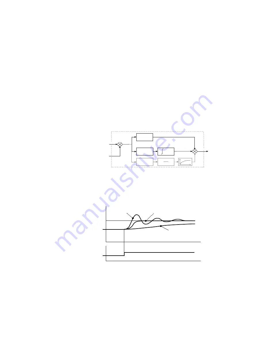
A Method for Setting-up the PI Gains
The gains should be set-up so that a critically damped response is achieved for a step change in
setpoint. An underdamped or oscillatory system can be thought of as having too much gain, and
an overdamped system has too little.
To set up the P gain, set the I gain to zero. Apply a step change in setpoint that is typical for the
System, and observe the response. Increase the gain and repeat the test until the system becomes
oscillatory. At this point, reduce the P gain until the oscillations disappear. This is the maximum
value of P gain achievable.
If a steady state error is present, i.e. the feedback never reaches the setpoint value, the I gain
needs to be increased. As before, increase the I gain and apply the step change. Monitor the
output. If the output becomes oscillatory, reduce the P gain slightly. This should reduce the
steady state error. Increasing the I gain further may reduce the time to achieve zero steady state
error.
These values of P and I can now be adjusted to provide the exact response required for this step
change.
Underdamped (oscillatory)
Critically Damped
Overdamped
OUTPUT
SETPOINT
P G a in
I G a in
d t
S e tp o in t
E r r o r
+
-
+
+
O u tp u t
F e e d b a c k
( A IN 2 )
( A IN 1 )
D G a in
d t
d
+


