background image

- 2 -

7.4 T

IMED 

A

UTO 

A

RMING

............................................................................................................................................................................................. 23

7.5 N

M

OVEMENT 

A

UTO 

A

RMING

............................................................................................................................................................................. 23

7.6 A

UTO 

A

RMING 

O

PTIONS

......................................................................................................................................................................................... 24

7.7 O

NE

-T

OUCH 

F

EATURES

........................................................................................................................................................................................... 24

7.8 E

XIT 

D

ELAY

.............................................................................................................................................................................................................. 24

7.9 K

EYPAD 

L

OCK

-O

UT 

F

EATURE

............................................................................................................................................................................... 24

7.10 M

AXIMUM 

B

YPASS 

E

NTRIES

................................................................................................................................................................................ 25

7.11 D

ISPLAY 

“B

YPASS

” I

A

RMED

............................................................................................................................................................................ 25

7.12 B

ELL 

S

QUAWK

....................................................................................................................................................................................................... 25

7.13 R

ING

-B

ACK

............................................................................................................................................................................................................. 25

7.14 S

WITCH TO 

S

TAY 

A

RMING

.................................................................................................................................................................................... 25

 ALARM OPTIONS ........................................................................................................................................................................................................26

8.1 B

ELL

/A

LARM 

O

UTPUT

............................................................................................................................................................................................ 26

8.2 B

ELL 

C

UT

-O

FF 

T

IMER

............................................................................................................................................................................................. 26

8.3 T

AMPER 

R

ECOGNITION 

O

PTIONS

........................................................................................................................................................................... 26

8.4 K

EYPAD 

P

ANIC 

O

PTIONS

......................................................................................................................................................................................... 27

 EVENT REPORTING...................................................................................................................................................................................................28

9.1 R

EPORTING 

E

NABLED

............................................................................................................................................................................................. 29

9.2 R

EPORT 

C

ODES

......................................................................................................................................................................................................... 29

9.3 C

ENTRAL 

S

TATION 

P

HONE 

# .................................................................................................................................................................................. 31

9.4 P

ARTITION 

A

CCOUNT 

# ........................................................................................................................................................................................... 31

9.5 R

EPORTING 

F

ORMATS

............................................................................................................................................................................................. 32

9.6 E

VENT 

C

ALL 

D

IRECTION

........................................................................................................................................................................................ 32

9.7 R

ECENT 

C

LOSE 

D

ELAY

........................................................................................................................................................................................... 33

9.8 A

UTO 

T

EST 

R

EPORT

................................................................................................................................................................................................ 33

9.9 P

OWER 

F

AIL 

R

EPORT 

D

ELAY

................................................................................................................................................................................. 33

9.10 D

ISARM 

R

EPORTING 

O

PTIONS

.............................................................................................................................................................................. 33

9.11 Z

ONE 

R

ESTORE 

R

EPORT 

O

PTIONS

....................................................................................................................................................................... 33

9.12 P

AGER 

D

ELAY

........................................................................................................................................................................................................ 34

9.13 A

UTO 

R

EPORT 

C

ODE 

P

ROGRAMMING

................................................................................................................................................................. 34

 DIALER OPTIONS .......................................................................................................................................................................................................35

10.1 T

ELEPHONE 

L

INE 

M

ONITORING

........................................................................................................................................................................... 35

10.2 T

ONE

/P

ULSE 

D

IALING

........................................................................................................................................................................................... 35

10.3 P

ULSE 

R

ATIO

.......................................................................................................................................................................................................... 35

10.4 B

USY 

T

ONE 

D

ETECTION

....................................................................................................................................................................................... 35

10.5 S

WITCH TO 

P

ULSE

.................................................................................................................................................................................................. 35

10.6 B

ELL ON 

C

OMMUNICATION 

F

AIL

.......................................................................................................................................................................... 35

10.7 D

IAL 

T

ONE 

D

ELAY

................................................................................................................................................................................................ 35

 PROGRAMMABLE OUTPUTS ................................................................................................................................................................................36

11.1 PGM A

CTIVATION 

E

VENT

................................................................................................................................................................................... 36

11.2 PGM D

E

-

ACTIVATION 

O

PTION

............................................................................................................................................................................ 36

11.3 PGM1 

IS 

S

MOKE 

I

NPUT

........................................................................................................................................................................................ 37

 SYSTEM SETTINGS & COMMANDS ...................................................................................................................................................................41

12.1 H

ARDWARE 

R

ESET

................................................................................................................................................................................................ 41

12.2 S

OFTWARE 

R

ESET

.................................................................................................................................................................................................. 41

12.3 B

ATTERY 

C

HARGE 

C

URRENT

............................................................................................................................................................................... 42

12.4 I

NSTALLER 

C

ODE 

L

OCK

........................................................................................................................................................................................ 42

12.5 S

YSTEM 

G

UARD 

L

OCK

.......................................................................................................................................................................................... 42

12.6 P

ARTITIONING

........................................................................................................................................................................................................ 42

12.7 I

NSTALLER 

F

UNCTION 

K

EYS

................................................................................................................................................................................ 42

12.8 S

YSTEM 

D

ATE 

& T

IME

.......................................................................................................................................................................................... 43

12.9 S

HABBAT 

F

EATURE

............................................................................................................................................................................................... 43

12.10 M

ODULE 

R

ESET

................................................................................................................................................................................................... 43

12.11 L

OCATE 

M

ODULE

................................................................................................................................................................................................ 43

12.12 M

ODULE 

P

ROGRAMMING

................................................................................................................................................................................... 43

Summary of Contents for Digiplex

Page 1: ...Digiplex Control Panel Reference Installation Manual ...

Page 2: ...11 PROGRAMMING METHOD 12 3 1 UPLOAD DOWNLOAD SOFTWARE 12 3 2 PROGRAMMING MODE 12 3 3 PROGRAMMING BUS MODULES 12 ACCESS CODES 13 4 1 INSTALLER CODE 13 4 2 ACCESS CODE LENGTH 13 4 3 SYSTEM MASTER CODE 13 4 4 USER OPTIONS 13 4 5 USER PARTITION ASSIGNMENT 14 4 6 MULTIPLE ACTION FEATURE 14 ZONE PROGRAMMING 15 5 1 ZONE NUMBERING 16 5 2 ZONE DEFINITIONS 16 5 3 ZONE PARTITION ASSIGNMENT 17 5 4 ZONE OPTION...

Page 3: ...TEST REPORT 33 9 9 POWER FAIL REPORT DELAY 33 9 10 DISARM REPORTING OPTIONS 33 9 11 ZONE RESTORE REPORT OPTIONS 33 9 12 PAGER DELAY 34 9 13 AUTO REPORT CODE PROGRAMMING 34 DIALER OPTIONS 35 10 1 TELEPHONE LINE MONITORING 35 10 2 TONE PULSE DIALING 35 10 3 PULSE RATIO 35 10 4 BUSY TONE DETECTION 35 10 5 SWITCH TO PULSE 35 10 6 BELL ON COMMUNICATION FAIL 35 10 7 DIAL TONE DELAY 35 PROGRAMMABLE OUTPU...

Page 4: ...AC FAIL DISPLAY 44 UPLOAD DOWNLOAD SOFTWARE 45 13 1 PANEL ANSWER OPTIONS 45 13 2 PANEL IDENTIFIER 45 13 3 PC PASSWORD 45 13 4 PC TELEPHONE NUMBER 45 13 5 CALL UPLOAD DOWNLOAD SOFTWARE 45 13 6 ANSWER UPLOAD DOWNLOAD SOFTWARE 46 13 7 EVENT BUFFER TRANSMISSION 46 13 8 CALL BACK FEATURE 46 USER KEYPAD FEATURES 47 INDEX 48 ...

Page 5: ...entry exit delay bell squawk quick arming panics and many more All zones keyswitches user codes and keypads are assigned to specific partitions making this a true partitioned system 63 User Codes 1 Installer 1 Master 4 fully programmable outputs PGMs PGM1 can be set as a 2 wire smoke detector input Optional 5A relay also available Simple direct and logical programming Event Call Direction The Digi...

Page 6: ...atent pending pet friendly lens There s no need to compromise performance or detector sensitivity to deliver pet immunity Impulse Wireless Zone Module DGP 319 Connected to the DIGI BUS this module will allow you to add 16 wireless zones using the LiberatorTM detectors and door contacts as well as 16 remote controls This module also includes two programmable 5A relays DigiPrint coming soon Connecte...

Page 7: ...In order to provide power during power loss connect a 12VDC 7Ah rechargeable acid lead or gel cell back up battery as shown in figure 2 2 Connect the back up battery after applying AC power When installing verify proper polarity as reversed connections will blow the battery fuse For information on how to set the Battery Charge Current to either 350mA or 700mA please refer to section 12 3 of this m...

Page 8: ... 7 ...

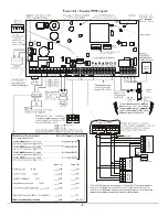
Page 9: ...re normally open outputs and PGM5 is a normally open or normally closed 5A relay Also note that PGM1 can be programmed as 2 wire smoke detector input For more information refer to sections 2 15 1 and 11 3 of this manual 2 9 BUS ZONE CONNECTIONS The DIGI BUS is a 4 wire communication bus that provides power and two way communication between the control panel and all modules connected to it All bus ...

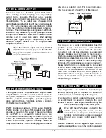
Page 10: ... four hardwired input terminals to the control panel see section 2 13 Devices connected to hardwired input terminals must be assigned to a zone and the zone s parameters must be defined Please refer to Zone Programming in section 5 of this manual for more information Figure 2 5 demonstrates single zone ATZ disabled hardwire input terminal connections recognized by the Digiplex system 2 12 DOUBLE Z...

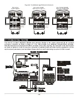
Page 11: ...e ZX4 provides four additional hardwired input terminals Detection devices are connected to the ZX4 s terminals in the same way they are connected to the control panel as shown in figures 2 5 and 2 6 Devices connected to hardwired input terminals must be assigned to a zone and the zone s parameters must be defined Please refer to Zone Programming in section 5 of this manual ...

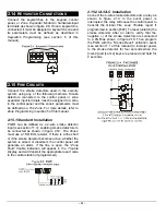
Page 12: ...ectors to be connected as shown in figure 2 12 Fire Zones must use a 1KΩ EOL resistor If there is a line short or if the smoke detector becomes active whether the system is armed or disarmed the control panel will generate an alarm If the line is open the Zone Fault trouble indication will appear in the Trouble Display and will transmit the appropriate report code to the central station if program...

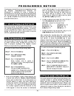
Page 13: ...ons may require the entry of one or more Hexadecimal values from 0 to F 0 to 9 values 0 to 9 respectively STAY key A DISARM key D FORCE key B BYP key E ARM key C MEM key F Certain sections may require the entry of a 3 digit Decimal value from 000 to 255 After entering the required data the control panel will save the data and automatically advance to the next section or press the ENTER key to save...

Page 14: ...rtitions and can program all User Access Codes User Options and User Partition Assignments The System Master Code can use any digits from 0 to 9 The length of the System Master Code is determined by the Access Code Length feature see section 4 2 above The System Master Code cannot be set to less than 4 digits in length 4 3 1 System Master Code Reset Using the Installer Code enter section 950 to re...

Page 15: ...IGNMENT Sections 802 to 864 Options 1 to 4 Each of the 63 User Access Codes can be assigned to one or more partitions A user can only arm disarm and view status of assigned partitions Select one or more of the partitions for each User Access Code as shown in figure 4 1 The System Master Code or a user with the Master Feature enabled can also program the User Partition Assignment using a different ...

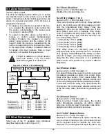
Page 16: ...IAL NUMBER of the bus detection device or of the module to which a hardwire device is connected Enter 3 digit INPUT NUMBER of module to which device is connected NOTE For motion detectors and keypads no input is required Key in INSTALLER CODE Zone Definitions 0 Disabled 6 Instant 1 Entry Delay 1 7 24Hr Buzzer 2 Entry Delay 2 8 24Hr Burglary 3 Entry Delay 3 9 Delayed 24Hr Fire 4 Entry Delay 4 A Sta...

Page 17: ...ns 101 148 First digit 0 Disables the corresponding zone 5 2 2 Entry Delays 1 to 4 Sections 101 148 First digit 1 to 4 When an armed zone with the Entry Delay definition opens the control panel will not generate an alarm until the programmed Entry Delay Timer has elapsed A zone can be defined with one of four Entry Delays each with a separate Entry Delay Timer To program the Entry Delay Timer key ...

Page 18: ...the appropriate Zone Alarm report code see section 9 2 5 to the central station If a tamper wiring fault occurs on a Fire Zone the control panel can send a Global Fire Loop Trouble Report see section 9 2 11 to the Central Station A Zone Fault Trouble will also appear in the keypad s Trouble Display Fire alarms are always audible regardless of other settings Fire alarms will generate an intermitten...

Page 19: ...nd the system must be disarmed A Report Only will send the report code to the central station Unlike a silent alarm no access codes are required to cancel the alarm Fire Zones cannot be set to report only 5 4 6 Intellizone Sections 101 148 Option 7 If an alarm condition occurs on a zone with option 7 enabled the control panel will trigger the Intellizone Delay and will seek confirmation of the ala...

Page 20: ...al ZX4 On Board Zone Expander see section 2 13 for details 209 ZX4 Terminal 1 Input 009 speed 210 ZX4 Terminal 2 Input 010 speed 211 ZX4 Terminal 3 Input 011 speed 212 ZX4 Terminal 4 Input 012 speed 213 ZX4 Doubler 1 Input 013 speed 214 ZX4 Doubler 2 Input 014 speed 215 ZX4 Doubler 3 Input 015 speed 216 ZX4 Doubler 4 Input 016 speed 5 6 EOL ZONES Section 504 Option 7 If detection devices connected...

Page 21: ...ent and its arming method see sections6 2 to 6 4 Press hold the 0 key Keyswitch Definition First Digit Keyswitch Partition Assignment Second Digit Keyswitch Options Feature Select Enter 8 digit SERIAL NUMBER of module to which keyswitch is connected Enter 3 digit INPUT NUMBER of module to which keyswitch is connected Key in INSTALLER CODE Press ENTER Figure 6 1 Keyswitch Programming Key in 3 digit...

Page 22: ...ption see section 6 4 determines the type of arming 6 2 3 Maintained Keyswitch Sections 149 156 First digit 2 To arm a partition using the Maintained Keyswitch turn the switch from the on to the off position To disarm a partition set the keyswitch in the on position In the case of an Arm Only option the control panel will not perform any action when the switch is in the on position The selected Ke...

Page 23: ...ions 149 156 Option 8 This option is identical to Stay Arming except that all armed zones will become Instant Zones see section 5 2 4 For more information on Instant Arming refer to section 14 6 4 5 Regular Arming Keyswitch 149 to 156 Option 6 to 8 When options 6 to 8 are off the keyswitch arming option will default to Regular Arming see section 14 ...

Page 24: ...ing day The type of arming is determined by the Auto Arming Option see section 7 6 Regardless of whether the partition was successfully armed or not the control panel will always transmit the Late to Close report code programmed in section 618 Since the control panel can enable this feature for each individual partition select the section that corresponds to the desired partition and turn on optio...

Page 25: ...d hold the STAY key for 2 seconds to Stay Arm see section 14 Option 3 ON Press and hold the 5 key for 2 seconds to Instant Arm see section 14 Option 4 ON Press and hold the FORCE key for 2 seconds to Force Arm see section 14 Option 5 ON Press and hold the DISARM key for 2 seconds to Disarm a Stay or Instant armed partition see section 14 Option 6 ON Press and hold the BYP key for 2 seconds to perf...

Page 26: ...of the 60 second period the bell or siren will emit three half second squawks at 1 second intervals Turning off option 3 will disable this feature Option 4 ON BELL SQUAWK DURING EXIT DELAY The bell or siren will emit half second squawks at 1 second intervals during the Exit Delay period During the final 10 seconds of the Exit Delay the bell or siren will emit three half second squawks at 1 second ...

Page 27: ...partition program the Recycle Delay from 001 255 minutes 000 disabled Where sections 246 to 249 represent partitions 1 through 4 The Recycle Delay is the amount of time after Bell Cut off the control panel will wait before re verifying the zone status 8 3 TAMPER RECOGNITION OPTIONS Section 501 Options 5 6 If a tamper or wire fault occurs in an armed partition regardless of the Tamper Recognition O...

Page 28: ...l generate a silent or audible alarm as defined by option 5 Option 3 ON PANIC 3 Pressing the 7 9 keys simultaneously on the keypad for 2 seconds will generate a silent or audible alarm as defined by option 6 Option 4 ON Panic 1 Silent OFF Panic 1 Audible Option 5 ON Panic 2 Silent OFF Panic 2 Audible Option 6 ON Panic 3 Silent OFF Panic 3 Pulsed Fire Silent operation The control panel emits a sing...

Page 29: ... number Continuing this sequence until each number has been dialed at least once Reporting Formats Section 550 1st digit CSTN 1 2nd digit CSTN 2 3rd digit CSTN 3 4th digit CSTN 4 Related Features Delay Before Alarm Transmission Section 256 Pager Format Delay Transmission Section 259 Recent Closing Delay Section 219 Power Failure Report Delay Section 260 Auto Test Report Sections 261 270 Report Dis...

Page 30: ...ser Access Codes and 8 keyswitch zones When using an access code or keyswitch to arm one or more partitions the control panel can send the appropriate report code to the central station identifying which access code or keyswitch zone was used to arm the partition s 9 2 2 Special Arming Report Codes Sections 618 to 619 Whenever the system is armed using one of the special arming features listed bel...

Page 31: ...e fault occurs on a zone the control panel can send the appropriate report code to the central station identifying which zone was tampered If the Tamper Recognition Options see section 8 3 are disabled the control panel will not report the occurrence of any tampers or wire faults 9 2 9 Zone Tamper Restore Codes Sections 677 to 688 A report code can be programmed for each of the forty eight availab...

Page 32: ... type of system occurrence Section 701 Cold Start the control panel was completely shutdown total power loss and the control panel was re started Warm Start the control panel performs a reset due to any sudden problem other than power loss Test Report a test report has been generated automatically see section 9 8 Section 702 Upload Download Software Access the control panel has ended communication...

Page 33: ...code from the Automatic Report Code List in the Programming Guide To automatically program a set of default contact ID codes refer to section 9 13 of this manual 9 5 4 SIA FSK SIA FSK is a fast communicator format that uses tone reporting instead of pulse reporting This communicator format uses a pre defined list of industry standard messages and report codes that will suit most of your basic inst...

Page 34: ...section 270 9 8 1 Hourly Test Transmission Section 522 Option 3 Alternatively the control panel can transmit the test report code programmed into section 701 every hour Turn off option 3 to disable this feature Program the minute of each hour it sends the test report into section 270 9 9 POWER FAIL REPORT DELAY Section 260 001 255 minutes The control panel will delay transmission of the AC Failure...

Page 35: ...tion 791 ARMING DISARMING CODES Sets all report codes in sections 600 to 638 with the default values from the Automatic Report Codes List in the Programming Guide Section 792 ALARM RESTORE CODES Sets all report codes in sections 639 to 664 with the default values from the Automatic Report Codes List in the Programming Guide Section 793 TAMPER TAMPER RESTORE CODES Sets all report codes in sections ...

Page 36: ... into section 255 Entering a value between 000 and 016 will set the TLM fail timer to 32 seconds 10 2 TONE PULSE DIALING Section 521 Option 4 By turning on option 4 the control panel can dial and transmit information using the tone DTMF format If option 4 is off the control panel will use the pulse dialing format Refer to section 10 3 below for setting the pulse ratio 10 3 PULSE RATIO Section 521 ...

Page 37: ...g the second digit use the feature select method enable disable options 1 to 8 to select up to eight specific events as detailed in the PGM Programming Table For details on the available activation events please refer to the PGM Programming Table Below you will find brief details on just a few of the available activation events Smoke Reset Activates the PGM for a period of 4 seconds every time the...

Page 38: ...GM5 409 PGM3 405 2 Follow steps 2 to 4 in section 11 1 If the PGM De activation Option is set for Timed the PGM will ignore the PGM De activation Event 11 2 2 PGM Delay Sections 241 to 250 000 255 To program the PGM Delay enter the section that corresponds to the desired PGM Delay where sections 250 to 254 represent PGM1 to PGM5 respectively and enter a value from 001 to 255 000 5 The value entere...

Page 39: ...Bus Com Fail 5 6 N A N A N A N A N A N A N A N A N A N A 0 00 00 00 15 00 30 00 45 01 00 01 15 01 30 01 45 1 02 00 02 15 02 30 02 45 03 00 03 15 03 30 03 45 2 04 00 04 15 04 30 04 45 05 00 05 15 05 30 05 45 3 06 00 06 15 06 30 06 45 07 00 07 15 07 30 07 45 4 08 00 08 15 08 30 08 45 09 00 09 15 09 30 09 45 5 10 00 10 15 10 30 10 45 11 00 11 15 11 30 11 45 6 12 00 12 15 12 30 12 45 13 00 13 15 13 30...

Page 40: ... 38 Zone 39 Zone 40 B Zone is Open D Zone 41 Zone 42 Zone 43 Zone 44 Zone 45 Zone 46 Zone 47 Zone 48 0 Zone 1 Zone 2 Zone 3 Zone 4 Zone 5 Zone 6 Zone 7 Zone 8 1 Zone 9 Zone 10 Zone 11 Zone 12 Zone 13 Zone 14 Zone 15 Zone 16 2 Zone 17 Zone 18 Zone 19 Zone 20 Zone 21 Zone 22 Zone 23 Zone 24 3 Zone 25 Zone 26 Zone 27 Zone 28 Zone 29 Zone 30 Zone 31 Zone 32 4 Zone 33 Zone 34 Zone 35 Zone 36 Zone 37 Zo...

Page 41: ...e 23 Zone 24 B Zone 25 Zone 26 Zone 27 Zone 28 Zone 29 Zone 30 Zone 31 Zone 32 C Zone 33 Zone 34 Zone 35 Zone 36 Zone 37 Zone 38 Zone 39 Zone 40 Second Digit Fire Burg Restore D Zone 41 Zone 42 Zone 43 Zone 44 Zone 45 Zone 46 Zone 47 Zone 48 0 Bus Fault Module Tamper ROM error Module TLM Fail to comm Printer Fault AC Fail Battery Fail 1 Auxiliary Output fail N A N A N A N A N A N A N A 8 Bus Fault...

Page 42: ...a system using 3 partitions Partitions 1 to 3 are enabled Bell Siren Output is enabled for partitions 1 to 3 Zone 1 is Entry Delay1 Partition 1 and Bypass enabled Zones 2 3 are Follow Partition 1 and Bypass enabled Zones 4 to 16 are Instant Partition 1 and Bypass enabled Zone 17 is Entry Delay2 Partition 2 and Bypass enabled Zones 18 19 are Follow Partition2 and Bypass enabled Zones 20 to 32 are I...

Page 43: ...stem the control panel will automatically recognize the new modules and lock them to the system You can remove locked devices and install them in another system as long as the Central Station Telephone Numbers are the same To enable this feature simply enter section 900 The lock sequence can only be cancelled by re entering section 990 before the end of the eight days Once enabled you can not remo...

Page 44: ...nnected to the DIGI BUS to its default values key in the module s serial number into section 951 12 11 LOCATE MODULE Section 952 If you wish to locate a specific module e g detector zone expander etc connected to the DIGI BUS key in the module s serial number into section 952 The green LOCATE LED on the module will begin to flash until the serial number is re entered into section 952 or the approp...

Page 45: ...ROUBLE SHUTDOWN Section 218 001 015 000 disabled If in a 24 hour period a trouble has occurred more than the number of times programmed in section 218 the control panel will no longer report this trouble Please note that each trouble its own counter This counter is reset every day at midnight or when a Module Scan is performed see section 12 7 of this manual Also note that it can not be set to mor...

Page 46: ...l panel will wait before picking up the line If the line is not answered after the number of programmed rings the control panel will answer the call Note the control panel resets the ring counter every 10 seconds Therefore if there is more than 10 seconds between each ring the control panel will reset the counter on the next call 13 2 PANEL IDENTIFIER Section 555 This four digit code identifies th...

Page 47: ...tem establishes communication it will upload the contents of the event buffer to the Upload Download software If communication is interrupted before completing transmission or if after two attempts communication is not established the system will wait until the event buffer attains another 50 capacity before attempting to re communicate with the central station When the Event Buffer is full each s...

Page 48: ... E Y P A D F E A T U R E S This section will be included in future revisions of this manual For the moment all information that has been referenced to this section can be found in the appropriate Keypad s User Guide ...

Page 49: ...r shall be given adequate notice to effect the modifications to maintain uninterrupted service GENERAL This equipment shall not be used on coin telephone lines Connection to party line service is subject to state tariffs RINGER EQUIVALENCE NUMBER REN The ren is useful to determine the quantity of devices that you may connect to your telephone line and still have all of those devices ring when your...

Page 50: ...MATÉRIEL L étiquette d Industrie Canada identifie le matériel homologué Cette étiquette certifie que le matériel est conforme à certaines normes de protection d exploitation et de sécurité des réseaux de télécommunications Le Ministère garantir toutefois pas que le matériel fonctionnera à la satisfaction de l utilisateur Avant d installer ce matériel l utilisateur doit s assurer qu il est permis d...

Page 51: ...Hr 16 Bypass Arming 14 Bypass Enabled 18 C Call Back Feature 46 Call Direction 32 Call Espload 45 Central Station Telephone Numbers 31 Connecting Keyswitches 11 Connecting the ZX4 10 Control Panel Programming 12 Current Setting for Battery Charging 42 D Daylight Savings Time 43 Delay Before Transmission 18 Delay Between Dialing Attempts 33 Delayed 24Hr Fire Zones 17 Dial Tone Delay 35 Dialer Optio...

Page 52: ...Module Programming 43 Module Reset 43 Momentary Keyswitch 21 Multiple Action Feature 14 N No AC Fail Trbl Display 44 No Arming On Power Failure 23 No Arming On Tamper Trouble 23 No Bell Cut Off on Fire Alarm 26 No Exit Delay on Remote Arm 24 No Movement Auto Arming 23 O One Touch Features 24 P Pager Delay 34 Pager Reporting Format 32 Panel Answer Options 45 Panel Identifier 45 Panic Options 27 Par...

Page 53: ... Telephone Line Connection 6 Telephone Number PC 45 Testing the battery 6 Timed Auto Arming 23 TLM Fail Timer 35 Tone Pulse Dialing 35 Twenty Four Hour Burglary Zones 17 Twenty Four Hour Buzzer Zones 16 Twenty Four Hour Delayed Fire Zones 17 Twenty Four Hour Standard Fire Zones 17 Types of Alarms 18 U Upload Download Software 45 User Code Priorities Arm Only 14 Bypass Arming 14 Duress 14 Master Us...

Page 54: ......

Reviews: