


796
DP-C405/C305/C265
FEB 2008
Ver. 1.1
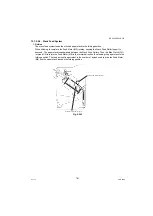
12.1.2.6.2. Punching Operation
1. Outline
The Punch Unit is located in the pickup assembly of the Finisher, and is used to punch holes in sheets
that have been sent from the Host Machine and stopped inside it. When the trailing edge of a sheet
reaches the Punch Unit, the Inlet Roller of the Finisher Assembly stops the sheet to punch a hole along
the trailing edge of the sheet.
The Punch Unit consists of a Die and Hole Puncher (Punch Blade).
The Hole Puncher is driven by the Punch Motor (M1P). It is attached to the Eccentric Cam of the Punch
Shaft, and the rotation of the Punch Shaft is converted into reciprocating motion for punching
operation.
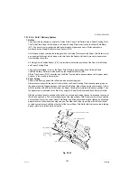
The Punch Motor (M1P) is a DC motor. The home position of the Punch Shaft is detected by the Punch
Home Position Sensor (PI1P). To make sure that the Punch Motor, which is a DC motor, stops exactly
at its home position, the Punch Motor is stopped in relation to the count of the clock pulses kept by the
Punch Motor Clock Sensor (PI3P).
A single punching operation is executed by rotating punch shaft 180° from its home position.
As many as five light-receiving transistors (Photo Sensor PCB) are mounted over the inlet paper path
of the Punch Unit; on the other hand, as many as five LEDs (LED PCB) are mounted under the path,
together serving as five Sensors. The Frontmost Sensor (LED5, PT5) is used to detect the training
edge of sheets, and the remaining four (LED1 through LED4, PT1 through PTR4) are used as
Horizontal Registration Sensors to detect the rear position of sheets when punching holes.
The Punch Motor, Punch Unit, and Sensors make up the Punch Slide Unit, which moves to the Front/
Rear to suit the selected paper size. The movement to the Front/Rear is driven by the Horizontal
Registration Motor (M2P). The home position of the Punch Slide Unit is detected by the Horizontal
Registration Home Position Sensor (PI2P), and the Horizontal Registration Motor (M2P) is a Stepping
Motor.
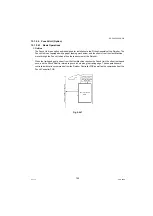
The Punch Motor and Horizontal Registration Motor are controlled with various commands from the
Finisher Controller PCB as well as the commands from the Punch Controller PCB.
The waste paper occurring as the result of punching is collected in the Waste Paper Case. The case is
monitored by the LED121 on the Waste Full LED PCB and PT131 on the Waste Full Photo Sensor
PCB.
Summary of Contents for Workio DP-C305
Page 2: ...2...
Page 3: ...3...
Page 5: ...5...
Page 6: ...6 For PB and Other Destinations not for PU USA Canada...
Page 11: ...11...
Page 12: ...12...
Page 13: ...13...
Page 14: ...14 memo...
Page 220: ...220 FEB 2008 Ver 1 1 DP C405 C305 C265 Color Test Chart 101 P N PJQRC0119Z LDR PJQRC0120Z A3...
Page 232: ...232 FEB 2008 Ver 1 1 DP C405 C305 C265 3 20 720K PM Kit DQ M35S72 DQ M32N72...
Page 400: ...400 FEB 2008 Ver 1 1 DP C405 C305 C265 LVPS CN6 LVPS CN7 Refer to SCN PC Board...
Page 401: ...401 FEB 2008 Ver 1 1 DP C405 C305 C265 LVPS CN8 Europe Specification Only...
Page 404: ...404 FEB 2008 Ver 1 1 DP C405 C305 C265 CST PCB CN603 CST PCB CN604...
Page 405: ...405 FEB 2008 Ver 1 1 DP C405 C305 C265 CST PCB CN605...
Page 406: ...406 FEB 2008 Ver 1 1 DP C405 C305 C265...
Page 407: ...407 FEB 2008 Ver 1 1 DP C405 C305 C265 CST PCB CN606...
Page 408: ...408 FEB 2008 Ver 1 1 DP C405 C305 C265...
Page 409: ...409 FEB 2008 Ver 1 1 DP C405 C305 C265 CST PCB CN607...
Page 410: ...410 FEB 2008 Ver 1 1 DP C405 C305 C265 CST PCB CN608...
Page 412: ...412 FEB 2008 Ver 1 1 DP C405 C305 C265 TRU PCB CN613...
Page 414: ...414 FEB 2008 Ver 1 1 DP C405 C305 C265 RLB PCB CN176...
Page 615: ...615 DP C405 C305 C265 FEB 2008 Ver 1 1 1 2 3 4 5 6 7 8...
Page 752: ...752 FEB 2008 Ver 1 1 DP C405 C305 C265 memo...
Page 847: ...847 DP C405 C305 C265 FEB 2008 Ver 1 1 2 Motor PCBs Fig 5 009 M1 M2 M8 M5 M4 M3 M7 M6 1...
Page 919: ......
Page 920: ...Published in Japan...


