46
6.4.
HOME SENSOR Board
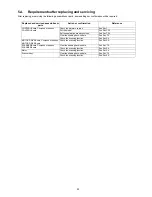
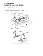
Before performing these section procedures, remove the following parts.
(1) Remove the Cover Lower Assy., Cover L, and Cover Lower L. (See 6.1.1.)
(2) Remove the Motor Drive Unit. (See 6.3.)
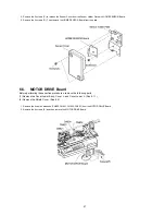
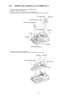
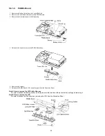
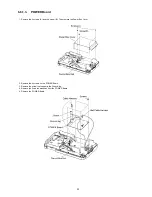
1. Remove the 4 screws (A) and then remove the Shield Cover.
2. Remove the Sensor Cable Harness(CN803) from the MOTOR DRIVE Board.
3. Remove the screw (B).
4. Remove the Home Sensor Assy. from the rear side of the Panaboard.
Summary of Contents for UB-5338C
Page 9: ...9 2 3 External View ...
Page 10: ...10 2 4 Control Panel Operation ...
Page 11: ...11 2 5 External Dimensions 2 5 1 UB 5838C ...
Page 12: ...12 2 5 2 UB 5338C ...
Page 101: ...101 13 Exploded View and Replacement Parts List ...
Page 102: ...102 13 1 Framework of Projected Diagram ...
Page 103: ...103 13 2 Cabinet Unit ...
Page 105: ...105 13 3 Motor Drive Unit Sensor Unit ...
Page 107: ...107 13 4 Control Box Unit ...
Page 109: ...109 13 5 Screen Feed Roller Unit ...
Page 111: ...111 13 6 Scanner Unit ...
Page 113: ...113 13 7 Panel Unit ...
Page 115: ...115 13 8 Frame Unit ...
Page 117: ...117 13 9 Rear Cover Unit ...
Page 119: ...119 13 10 Packing ...

