25
3.6.2.
Installing the Wall-Mounting Fixtures
Note:
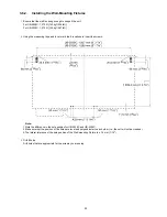
1. Note the difference in the hole position for UB-5838C and UB-5338C.
2. Make sure that the position of the holes are level and perpendicular to each other (i.e., the unit will not be crooked).
3. The lateral tolerance of the hole position of the Wall-mounting Fixture is ± 1.5 mm (1/16").
1.
Ensure that the wall is strong enough to support the unit.
For UB-5838C: 1,373 N [140 kgf (309 lbf)]
For UB-5338C: 1,275 N [130 kgf (287 lbf)]
2.
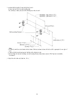
Using the measuring tape and level, mark the 8 locations to insert the screws.
3.
Drill 8 holes.
Drill holes that are appropriate for the screws you are using.
Summary of Contents for UB-5338C
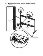
Page 9: ...9 2 3 External View ...
Page 10: ...10 2 4 Control Panel Operation ...
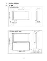
Page 11: ...11 2 5 External Dimensions 2 5 1 UB 5838C ...
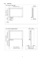
Page 12: ...12 2 5 2 UB 5338C ...
Page 101: ...101 13 Exploded View and Replacement Parts List ...
Page 102: ...102 13 1 Framework of Projected Diagram ...
Page 103: ...103 13 2 Cabinet Unit ...
Page 105: ...105 13 3 Motor Drive Unit Sensor Unit ...
Page 107: ...107 13 4 Control Box Unit ...
Page 109: ...109 13 5 Screen Feed Roller Unit ...
Page 111: ...111 13 6 Scanner Unit ...
Page 113: ...113 13 7 Panel Unit ...
Page 115: ...115 13 8 Frame Unit ...
Page 117: ...117 13 9 Rear Cover Unit ...
Page 119: ...119 13 10 Packing ...

