56
6.7.2.
Screen Sub-roller
Before performing these section procedures, remove the following parts.
(1) Remove the Cover Lower Assy. (See 6.1.1.)
(2) Remove the Cover Upper R and Cover R. (See 6.1.3.)
(3) Remove the Cover Lower R and Roller Unit Cover. (See 6.1.4.)
(4) Remove the Base Plate Support for the upper position, Base Plate Support for the lower position, and 2 springs. (See 6.7.1.)
Note:
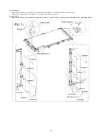
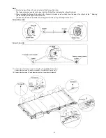
1. Must not remove Rings (A) on both sides of the Screen Sub-roller.
That removal may cause the pin to insert into the Roller Pipe to disable the roller attachment.
2. When installing the Screen Sub-roller to the Frame Unit, make sure to attach the side where the roller has the ** Bearing
(made of metal) to the upper side of the unit.
(This bearing is used as an earth connecting point for this unit by installing it to the unit.)
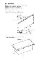
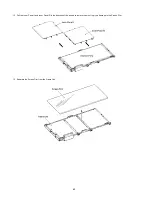
1. Remove the 2 screws (A) and then remove the Roller Tension Plate Under Assy.
2. Pull the Screen Sub-roller in the direction of the arrow to remove it.
Summary of Contents for UB-5338C
Page 9: ...9 2 3 External View ...
Page 10: ...10 2 4 Control Panel Operation ...
Page 11: ...11 2 5 External Dimensions 2 5 1 UB 5838C ...
Page 12: ...12 2 5 2 UB 5338C ...
Page 101: ...101 13 Exploded View and Replacement Parts List ...
Page 102: ...102 13 1 Framework of Projected Diagram ...
Page 103: ...103 13 2 Cabinet Unit ...
Page 105: ...105 13 3 Motor Drive Unit Sensor Unit ...
Page 107: ...107 13 4 Control Box Unit ...
Page 109: ...109 13 5 Screen Feed Roller Unit ...
Page 111: ...111 13 6 Scanner Unit ...
Page 113: ...113 13 7 Panel Unit ...
Page 115: ...115 13 8 Frame Unit ...
Page 117: ...117 13 9 Rear Cover Unit ...
Page 119: ...119 13 10 Packing ...


