31
5 Troubleshooting Guide
5.1.
Error Code
Error Code
Possible Cause
Check Point
Display
Code Name
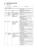
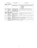
F505001
USB Host Error
USB Host (IC12) Access Error 1. Check the soldering condition of IC12 (USB Host) on the
CONTROL Board.
2. Replace the faulty part or CONTROL Board.
F505002
USB Device Error USB Device (IC13) Access
Error
1. Check the soldering condition of IC13 (USB Device) on the
CONTROL Board.
2. Replace the faulty part or CONTROL Board.
F506144
SD Memory Card
Write Error
Write Error to SD Memory
Card occurred while scanning
1. Confirm that write to the SD Memory is correctly performed
with a PC.
F507144
USB Flash
Memory Write
Error
Write Error to USB Flash
Memory occurred while
scanning
1. Confirm that write to the USB Flash Memory is correctly
performed with a PC.
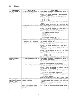
F603001
AFE Error
AFE (Analog Front End:
IC602) Access Error
1. Check the connection between CN606 (SCANNER Board)
and CN5 (CONTROL Board).
2. Check the soldering condition of IC602 (AFE) on the
SCANNER Board.
3. Check the soldering conditions of the following parts.
(1) IC6 (CONTROL Board)
(2) IC604 (SCANNER Board)
4. Replace faulty parts, SCANNER Board, or CONTROL
Board.
F603002
CIS Error
1. SOC (IC4: CONTROL
Board) did not receive the
signals from CIS.
2. CIS is broken.
3. LED isn’t on.
1. Check the connection between CN606 (SCANNER Board)
and CN5 (CONTROL Board).
2. Check the connection between CN4 (CONTROL Board)
and CN800 (MOTOR DRIVE Board).
3. Check the connection between CN604 (SCANNER Board)
and CN801 (MOTOR DRIVE Board).
4. Check the connection between CN605 (SCANNER Board)
and Scanner Assy.
5. Check the connections between CIS and CN600 to CN603
(SCANNER Board).
6. Check the soldering conditions of the following parts on the
SCANNER Board.
→
IC600, IC602 to IC610, IC614, and Q601 to Q606
7. Check the soldering conditions of the following parts on the
CONTROL Board.
→
IC6, IC7, IC8, and IC10
8. Replace faulty parts, Scanner Assy., SCANNER Board, or
CONTROL Board.
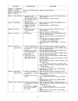
F603003
CIS Signal Error
(beyond the
specified level)
1. CIS signal is saturated due
to incoming light or sunlight
to the CIS.
2. CIS is broken.
3. CIS signal that SOC(IC14:
CONTROL Board) received
is saturated.
1. Check that the screen surface for shading is not dirty.
2. Check the connection between CN606 (SCANNER Board)
and CN5 (CONTROL Board).
3. Check the connection between CN4 (CONTROL Board)
and CN800 (MOTOR DRIVE Board).
4. Check the connection between CN604 (SCANNER Board)
and CN801 (MOTOR DRIVE Board).
5. Check the connection between CN605 (SCANNER Board)
and Scanner Assy.
6. Check the connections between CIS and CN600 to CN603
(SCANNER Board).
7. Check the soldering conditions of the following parts on the
SCANNER Board.
→
IC600, IC602 to IC610, IC614, and Q601 to Q606
8. Check the soldering conditions of the following parts on the
CONTROL Board.
→
IC6, IC7, IC8, and IC10
9. Replace faulty parts, Scanner Assy., SCANNER Board, or
CONTROL Board.
Summary of Contents for UB-5338C
Page 9: ...9 2 3 External View ...
Page 10: ...10 2 4 Control Panel Operation ...
Page 11: ...11 2 5 External Dimensions 2 5 1 UB 5838C ...
Page 12: ...12 2 5 2 UB 5338C ...
Page 101: ...101 13 Exploded View and Replacement Parts List ...
Page 102: ...102 13 1 Framework of Projected Diagram ...
Page 103: ...103 13 2 Cabinet Unit ...
Page 105: ...105 13 3 Motor Drive Unit Sensor Unit ...
Page 107: ...107 13 4 Control Box Unit ...
Page 109: ...109 13 5 Screen Feed Roller Unit ...
Page 111: ...111 13 6 Scanner Unit ...
Page 113: ...113 13 7 Panel Unit ...
Page 115: ...115 13 8 Frame Unit ...
Page 117: ...117 13 9 Rear Cover Unit ...
Page 119: ...119 13 10 Packing ...


