SF4C Safety light curtain
2.6 Wiring
39
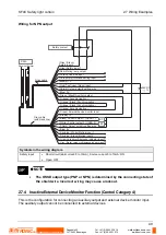
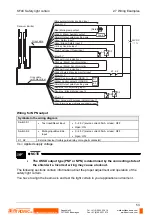
NOTE
•
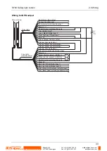
For wiring the safety input 1 wire (gray) and the safety input 2 wire
(gray/black), see "Inactive External Device Monitor Function (Control
Category 4)" on page 49.
•
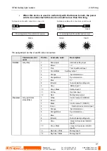
The large multipurpose indicator lights up in red when connecting the large
multi-purpose indicator input 1 wire (gray) and 0V, and it lights up in green
when connecting the large multi-purpose indicator input 2 wire (gray/black)
and 0V.
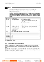
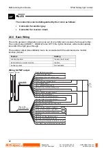
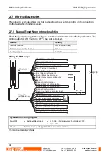
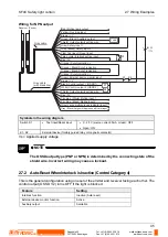
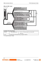
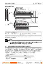
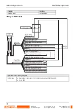
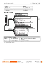
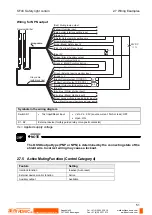
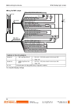
Symbols in the wiring diagram
Switch S1
•
Test
input/Reset
input
When manual reset is activated:
•
Vs to Vs - 2.5V (source current: 5mA or less): OFF
•
Open:
ON
When auto-reset is activated:
•
Vs to Vs - 2.5V (source current: 5mA or less): ON
•
Open: OFF
Switch S2
•
Interlock setting input,
Override input, Large
multi-purpose indicator
input 1/2, Muting input
1/2, External device
monitor input
•
Vs to Vs - 2.5 V (source current: 5mA or less): ON
•
Open: OFF
K1, K2
External device (forcibly guided relay or magnetic contactor)
Resistance A
3k
Ω
Resistance B
6.8k
Ω
Resistance C
470
Ω
Resistance D
47k
Ω
Condenser E
Condenser F
0.47
μ
F
0.1
μ
F
Vs = Applied supply voltage
2.6.4 Output Signal during Self-Diagnosis
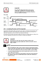
Since the receiver performs the self-diagnosis of the output circuit when the sensor is in
light-receiving status (ON status), the output transistor turns OFF periodically (see following
figure).
When the OFF signal is fed back, the receiver judges the output circuit as normal. When the
OFF signal is not fed back, the receiver judges either the output circuit or wiring as faulty, and
the control output (OSSD 1, OSSD 2) stays OFF.
Rugghölzli 2
CH - 5453 Busslingen
Tel. +41 (0)56 222 38 18
Fax +41 (0)56 222 10 12
www.sentronic.com
Produkte, Support und Service
SENTRONIC
AG


