background image

58

English

Set up timer

Sets the program to turn the power on with the specified 

time and video input, or to turn the power off at the 

specified time. Up to 20 programmes can be set.

Note

● 

When the current time is displayed as [- -], set [Date 

and time] before setting [Set up timer]. (see page 58)

● 

When multiple programs are set at the same time, 

the program with the smallest program number is 

enabled.

● 

If [Power mode] is set to [Power on], executing the 

program at power-on will switch to the input set for 

[Input].

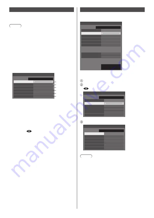
[Set up timer] - submenu screen
Setting Example:
Program 1, Every Monday, 12:00,
Power On, Input: HDMI1

12:00

Set up timer

Program

Timer function

1

On

Power on

HDMI1

Day

Time

Power mode

Input

MONDAY

1

2

3

4

5

6

10:00

SUNDAY

2017/01/01

1

Set the program number.

2

To execute the program, set to [On].
The program is disabled when [Off] is set.

3

Set the day.
The program is executed every day when 

[Everyday] is set.

4

Set the power On/Off.

5

Set the time.
Pressing     once changes time 1 minute.
Pressing continuously changes time by 15 

minutes.

6

Set the input.

Date and time

Set date and time. ([- -] shows no programme is set.)
[Date and time] - submenu screen

Date and time

Set

SUNDAY 10:00

2017/01/01

Year

2017

Month
Day
Hour
Minute

1
1

10

0

Synchronize display

Off

Parent or child setting

Child

Synchronize display setting

NTP synchronization

Off

Time zone

(GMT + 00:00)

NTP status


Set date and time

   Select  [Year / Month / Day / Hour / Minute].
  Set the selected item.


Date and time

Set

SUNDAY 10:00

2017/01/01

Year

2017

Month
Day
Hour
Minute

1
1

10

0

   Select  [Set] and press <ENTER>.

99:99

2015/01/01

Date and time

Set

SUNDAY 18:00

2017/02/05

Year

2017

Month
Day
Hour
Minute

2
5

18

0

Note

● 

If the present date and time are not set, the time 

settings for [Set up timer], [Screensaver], etc. cannot 

be made.

● 

The present date and time setting is reset in the 

following case.
When the main unit is left unattended for 7 days or 

longer after the main unit is turned off with the <Main 

Power On / Off button>, the power plug is removed, 

or power failure has occurred, etc.

● 

Date and time cannot be set when [Year / Month / 

Day / Hour / Minute] are set to [- -].

● 

The upper limit of date and time that can be set is, 

Year 2035, Month 12, Day 31, Hour 23 and Minute 

59.

Summary of Contents for SF2H Series

Page 1: ... model TH 80SF2HW 80 inch model TH 70SF2HW 70 inch model English Please read these instructions before operating your set and retain them for future reference This manual is common to all the models regardless of suffixes of the model number U for US Canada and Mexico W for EU CIS South East Asia and Middle East Asia DPQP1204ZB EU ...

Page 2: ...g Instructions are created mainly based on the 70 inch model Important Safety Instructions 4 FCC STATEMENT 5 Important Safety Notice 6 Safety Precautions 8 Precautions for use 11 Feature of This Unit 13 Accessories 13 Accessories Supply 13 Remote Control Batteries 14 Cautions when moving 14 Eyebolt 80 inch model 15 Connections 16 AC cord connection and fixing Cable fixing 16 Video equipment connec...

Page 3: ... Before Using Web Browser Control 86 Access from Web Browser 87 Operating with Web Browser 88 Using Web Browser Control 94 Using USB media player 96 Function description 96 Preparation 97 Playing back the files 99 Network environment Multi Media Player only 102 Starting ending Media Player 102 Resume Play function 103 Playlist edit function 103 Schedule playback function using Content Management S...

Page 4: ...o not block any ventilation openings Install in accordance with the manufacturer s instructions 8 Do not install near any heat sources such as radiators heat registers stoves or other apparatus including amplifiers that produce heat 9 Do not defeat the safety purpose of the polarized or grounding type plug A polarized plug has two blades with one wider than the other A grounding type plug has two ...

Page 5: ...ired operation CANADIAN NOTICE This Class A digital apparatus complies with Canadian ICES 003 WARNING Not for use in a computer room as defined in the Standard for the Protection of Electronic Computer Data Processing Equipment ANSI NFPA 75 For permanently connected equipment a readily accessible disconnect device shall be incorporated in the building installation wiring For pluggable equipment th...

Page 6: ...ce near sources of strong electromagnetic fields or where electrical noise may overlap with the input signals could cause the picture and sound to wobble or cause interference such as noise to appear To avoid the possibility of harm to this appliance keep it away from sources of strong electromagnetic fields WARNING This equipment is compliant with Class A of CISPR32 In a residential environment t...

Page 7: ...use is replaced If you lose the fuse cover the plug must not be used until a replacement cover is obtained A replacement fuse cover can be purchased from your local Panasonic dealer Do not cut off the mains plug Do not use any other type of mains lead except the one supplied with this display The supplied mains lead and moulded plug are designed to be used with this display to avoid interference a...

Page 8: ...ng played with by young children creating the potential risk of suffocation Do not place the Display on sloped or unstable surfaces and ensure that the Display does not hang over the edge of the base The Display may fall off or tip over Install this unit at a location with minimal vibration and which can support the weight of the unit Dropping or falling of the unit may cause injury or malfunction...

Page 9: ...ng so may cause short circuit generates heat etc which could cause electric shock or fire Do not use the supplied power supply cord with any other devices Doing so may cause short circuit generates heat etc which could cause electric shock or fire Clean the power supply plug regularly to prevent it becoming dusty If there is a build up of dust on the plug the resultant humidity may cause short cir...

Page 10: ...d result Disconnect the power supply plug from the wall socket as a safety precaution before carrying out any cleaning Electric shocks can result if this is not done Do not step on or hang from the display or the Pedestal They might tip over or might be broken and it may result in injury Pay special attention to the children Do not reverse the polarity and of the battery when inserting Mishandling...

Page 11: ...etting up method wall hanging etc follow the manual of it If there is no specific indication of installation dimension in the installation manual leave a space of 10 cm 3 15 16 or more at the top bottom left and right and 5 cm 1 31 32 or more at the rear Minimum distance a a b a 10 cm 3 15 16 b 5 cm 1 31 32 a Operation of this unit is guaranteed up to an ambient temperature of 40 C 104 F When inst...

Page 12: ...word directly Do not divulge your password in case you receive such inquiries The connecting network must be secured by a firewall etc When disposing the product initialize the data before disposing Shipping see page 125 LightID When using a laser barcode reader prevent a barcode surface from being exposed to the screen light The barcode reading may be impossible or incorrect When shooting the scr...

Page 13: ...Play by LinkRay and download the software For the latest information of devices for which normal operation has been confirmed see the Panasonic web site https panasonic net cns LinkRay Accessories Accessories Supply Check that you have the accessories and items shown Operating Instructions CD ROM 1 Remote Control Transmitter 1 DPVF1615ZA 4 pole mini plug conversion cable 1 DPVF1652ZA Batteries for...

Page 14: ...up batteries Moreover batteries must not be exposed to excessive heat such as sunshine fire or the like Cautions when moving The display has handles for carrying Hold them when moving Handle Note Do not hold parts other than the handles The following number of people are required to carry this unit 80 inch model 4 70 inch model 2 If this is not observed the unit may drop resulting in injury When c...

Page 15: ...yebolt commercially available mounting positions Note Installation should be performed by an installation professional Do not suspend using only 1 eyebolt Use commercially sold M10 eyebolts with a shank length of 12 mm to 25 mm that satisfies the load condition of product quality Use ISO 3266 standard eyebolts Also use ISO standard members wire etc for hanging The hanging angle should be 60 or mor...

Page 16: ...he dealer where you purchased the product When disconnecting the AC cord be absolutely sure to disconnect the AC cord plug at the socket outlet first The supplied AC cord is for this unit exclusive use Do not use this for other purposes Cable fixing Note 3 clampers are supplied with this unit Fix the cables at 3 locations using the holes for clampers as shown below If you need more clampers purcha...

Page 17: ...ed to supply power of up to 5V 1A to an external device when the picture is displayed see page 26 6 DVI D IN DVI D OUT DVI D Input Output Terminal Connect to video equipment with DVI D output Also when displaying the picture by daisy chaining multiple displays connect to the other display DVI D OUT The DVI D output function is enabled only for the DVI input Note this is not output if the HDMI or D...

Page 18: ...e a connection cable with the suitable plug size for the terminal alignment When connecting the LAN cable with plug cover be aware that the cover may come in contact with the back cover and it may be difficult to disconnect If video signals from video equipment contain too much jitter the images on the screen may wobble In this case a time base corrector TBC must be connected When the sync signals...

Page 19: ...nd 5V DC Hot Plug Detect DVI D IN DVI D OUT terminal connection Note Video equipment and cables shown are not supplied with this unit DVI D IN terminal is for Single Link only Audio input is shared with AV IN terminal Use the DVI D cable complying with the DVI standard Depending on the cable length or its quality noise may occur on images or the image quality may deteriorate DIGITAL LINK DVI D cab...

Page 20: ...n up to 8 displays The DVI D output function is enabled only for the DVI D input This is not output if the HDMI or DIGITAL LINK input is selected When using the daisy chain connection method all the displays should be in the state where the picture is displayed via DVI D IN Pin assignments and signal names for DVI D Input Output Pin No Signal Name T M D S data 2 T M D S data 2 T M D S data 2 shiel...

Page 21: ...e PC screen is not displayed check if the image signal of the PC meets Preset Signals see page 123 and then change the settings For power saving purpose image output may be OFF on a notebook computer In this case it may be set to ON with function key operation etc of the computer Refer to the manual of the computer Note Component video signal is supported with this terminal Mini D sub 15P Change t...

Page 22: ... pair cable transmitters such as the Panasonic Digital Interface Box ET YFB100G or the DIGITAL LINK Switcher ET YFB200G use twisted pair cables to transmit inputted video and audio signals and these digital signals can be input to the Display via the DIGITAL LINK terminal DIGITAL LINK Analogue signal is output as Digital signal PC to control the unit Example Panasonic ET YFB100G PC Video Cassette ...

Page 23: ... The SERIAL terminal conforms to the RS 232C interface specification so that the Display can be controlled by a computer which is connected to this terminal Note Additional computer and cables shown are not supplied with this set D sub 9p Female Male RS 232C Straight cable commercially available PC Note Select the RS 232C straight cable for communication used for connecting SERIAL terminal and com...

Page 24: ...meter Control details PON None Power ON POF None Power OFF AVL Volume 000 100 AMT 0 Audio MUTE OFF 1 Audio MUTE ON IMS None Input select toggle HM1 HDMI 1 input HDMI1 HM2 HDMI 2 input HDMI2 DL1 DIGITAL LINK input DIGITAL LINK DV1 DVI D IN input DVI D PC1 PC IN input PC VD1 AV IN input VIDEO UD1 USB input USB MV1 Memory viewer input MEMORY VIEWER DAM None Screen mode select toggle ZOOM Zoom1 FULL 1...

Page 25: ...rom the IR OUT terminal of the first display to the IR IN terminal of the second display The infrared signal of the first display is sent to the second display In this case the IR infrared ray reception on the remote control sensor on the second display does not operate Repeating the above connections enables the daisy chain connection Note Connection cables are not supplied with this unit Daisy c...

Page 26: ...lable to use USB media player or Memory viewer see page 96 108 Also power is supplied when a separately sold stick PC etc are connected Note A stick PC and connection cables are not supplied with this unit If the power is turned off or the USB memory device is removed while accessing data in the USB memory device the stored data may be destroyed The access indicator of the USB memory device blinks...

Page 27: ...ccess indicator of the connected USB memory device is blinking it shows the display is loading the data Do not remove the USB memory device while blinking Depending on the USB memory device the access indicator may remain blinking even when it is not being accessed or the device is not equipped with an access indicator function etc In this case remove the USB memory device after confirming the fol...

Page 28: ... page 51 When the power of the unit is OFF Main Power On Off button OFF No light Note Even if the unit is turned off with the power indicator off some of the circuits are in power on status When the power indicator is orange power consumption during standby is generally larger than that of when the power indicator is red MENU ENTER INPUT 8 8 70 inch model 80 inch model 1 External input output term...

Page 29: ... size of the screen see page 38 11 INPUT Switches input to display on the screen see page 31 12 PICTURE see page 41 13 SOUND see page 40 14 RECALL Displays the current setting status of Input mode Aspect mode etc see page 32 15 RETURN Used to return to the previous menu see page 36 16 FUNCTION Displays Function button guide see page 66 17 OFF TIMER Switches to stand by after a fixed period see pag...

Page 30: ...e saved if the power plug is disconnected immediately after changing settings with on screen menu Disconnect the power plug after a enough period of time Or disconnect the power plug after turning the power off with the remote control RS 232C control or LAN control 3 Press the Main Power On Off button on the unit to turn the power of the unit on Power Indicator Green Picture is displayed When the ...

Page 31: ...ge is displayed every time the power is turned ON see page 51 These message displays can be set with the following menu Options menu Power on message No activity power off see page 77 Power on message Power management see page 77 Selecting the input signal Select the signals input to the unit Press INPUT or INPUT Unit Unit MENU ENTER INPUT Switches input every time the buttons are pressed PC 16 9 ...

Page 32: ... No play file are not displayed Instead the image set in No signal image settings will be displayed To display the clock set Date and time and then set Clock display to On see page 58 76 Volume Adjustment Press VOL VOL or Unit Unit to adjust volume Unit MENU ENTER INPUT 20 Volume SPEAKERS The current sound volume level is memorised even if the power is turned off When Maximum VOL function is set t...

Page 33: ...ed After that it switches to stand by To see the Off timer remaining time press RECALL The Off timer is cancelled if a power interruption occurs When the power is turned on later on it will be in stand by condition When the image set in No signal image settings see page 55 is displayed remaining time is not displayed even when the timer expires in 3 minutes Instead the image is displayed until the...

Page 34: ...Letterbox pictures with a 16 9 aspect ratio are enlarged vertically and horizontally to fill the screen The top and bottom edges as well as the left and right edges of the pictures are cut off In ENGLISH US OSD language 16 9 is displayed as FULL Note This display incorporates several types of aspect mode select functions If a mode whose aspect ratio is different from that of TV program content is ...

Page 35: ...gain 4 Exit the digital zoom mode Press RETURN to exit the mode The screen returns to the previous state just before entering the digital zoom mode and the digital zoom operation guide display disappears Press any of the following buttons to exit the mode Then the operation of the pressed button is performed Remote Control AUTO SETUP POSITION PICTURE INPUT SETUP SOUND DEFAULT RECALL MUTE ASPECT OF...

Page 36: ...tness Colour Hue Sharpness Gamma Memory save Memory load Memory edit High Enhance level 6500K Colour temperature Dynamic contrast Colour enhancement Off Off Refine enhancer 6 segment colour management Gradation smoother Off Off To display the submenu press ENTER 3 Set Press to set MENU ENTER INPUT Press to set 4 Exit from the menu Press Press RETURN to return to the previous screen Alternatively p...

Page 37: ... smoother Off Off Picture Default Default Picture mode Standard Backlight Contrast Brightness Colour Hue Sharpness Gamma 2 2 Colour temperature 6500K Colour enhancement Dynamic contrast Memory save Memory load Memory edit Off Off Enhance level High Setup menu see page 47 67 1 2 Setup Screensaver Signal Input label Power management settings Wobbling No activity power off OSD language Off Disable En...

Page 38: ...ignal PC While displaying the picture of the corresponding signal select Auto setup and press ENTER Using Remote Control Press AUTO SETUP When Auto Setup does not work Invalid is displayed Note When the dot clock frequency of a PC signal is 162 MHz or higher Clock phase and Dot clock cannot be automatically corrected Auto Setup may not work when a cropped or dark image is input In such case switch...

Page 39: ...splayed If this happens adjust so that any such noise is minimized Over scan Turn image over scan On Off Applicable input signal 480 60i 480 60p 576 50i 576 50p 720 60p 720 50p On Off Note When Off is set H size and V size cannot be adjusted 1 1 pixel mode Adjusts the display size when 1080i or 1080p signal is input Off On Applicable input signal 1080 50i 60i 24PsF 24p 25p 30p 50p 60p Note Select ...

Page 40: ...efault Output select Select the audio output SPEAKERS Internal speakers AUDIO OUT AUDIO OUT terminal output When AUDIO OUT is selected the other menus are greyed out and cannot be selected Audio volume setting is memorized separately for each output Balance Adjusts left and right volumes Sound mode Select for best audio Normal Emits the original sound Dynamic Accentuates sharp sound Clear Attenuat...

Page 41: ...e to the picture source or environment where this unit is used Vivid signage Suitable for signage applications featuring more vivid and sharper images in bright environments such as a shop Natural signage Suitable for signage applications such as merchandise exhibition featuring natural tone images with colour reproduction emphasized under light Standard Faithfully reproduces original picture Surv...

Page 42: ... When DICOM is selected in Picture mode only 6500K and 9300K can be selected User setting of Colour temperature 2 kinds of detailed Colour temperature settings USER1 and USER2 can be stored 1 Press ENTER while setting Colour temperature 2 2 6500K Gamma Colour temperature Example When Colour temperature is 6500K it is possible to reflect the set point 6500K to the set point of USER1 and USER2 2 Sel...

Page 43: ...t with Hue Adjusts colour balance 511 to 511 Saturation Adjusts gradations of colour 127 to 127 Value Adjusts brightness of colour 127 to 127 Reset Resets to defaults Select Yes with and press ENTER In ENGLISH US OSD language Hue is displayed as TINT Dynamic contrast Automatically adjusts the contrast by determining the changes in the use of colours for images that constantly change such as motion...

Page 44: ...ion smoother Memory save Memory load Memory edit Off Off Off Off High Dynamic contrast 6 segment colour management Gamma 2 2 Memory save see page 45 Memory load see page 45 Memory edit see page 46 1 2 3 MEMORY1 MEMORY2 MEMORY3 4 MEMORY4 5 MEMORY5 6 MEMORY6 Overview of Picture Profiles Original picture Adjust picture see page 41 43 Custom picture Example Save the picture adjustment values in the ME...

Page 45: ... 9 a a A b c d e f g h i j k l m n o p q r s t u v w x y z _ Ok Cancel All delete Delete 6 When you finished entering the profile name select Ok with and press ENTER MY MEMORY1 0 1 2 3 4 5 6 7 8 9 a b c d e f g h i j k l m n o p q r s t u v w x y z _ a A Ok Cancel All delete Delete To cancel saving the profile select Cancel Loading profiles Load profiles and apply the picture adjustment values to ...

Page 46: ...l profiles select All delete 4 Select Ok with and press ENTER Memory delete Delete the MEMORY1 data Ok Cancel Renaming profiles 1 In the Picture menu select Memory edit with and press ENTER Memory save Memory load Memory edit 2 Select Memory name change with and press ENTER Memory edit Memory delete Memory name change 3 Select the profile to rename with and press ENTER 1 2 3 MEMORY1 MEMORY2 MEMORY...

Page 47: ...HDMI DVI DIGITAL LINK is selected 60 00 Hz 74 18 MHz 1080 60i 33 72 kHz Signal Cinema reality YUV RGB in select Noise reduction Signal range MPEG noise reduction Dynamic backlight control V freq H freq Dot clock freq Signal format Off YUV Auto Full 0 255 Off Off When PC is selected 60 00 Hz 74 18 MHz 1080 60i 33 72 kHz 0 Signal Component RGB in select Sync Cinema reality XGA mode V freq H freq Dot...

Page 48: ...ut terminal on Y Uses a synchronized signal on the Video Y signal which is input from the Y connector HV sync Uses a synchronized signal on the Video HD VD signal which is input from the HD VD connector Cinema reality Faithfully reproduces videos shot with cinema films Set this to Off normally Note In ENGLISH US OSD language Cinema reality is displayed as 3 2 PULLDOWN If Cinema reality is set to O...

Page 49: ...le When the system is set to Auto images become unstable in rare case under the condition that the input signals are at low level or have many noises In this case set the system so it conforms with the input signal format Dynamic backlight control Improves picture contrast and alleviates whiteness by controlling the back light when signals with the low average brightness level APL are input On Ena...

Page 50: ...own to change the time by 15 minutes In ENGLISH US OSD language Operating time is displayed as SAVER DURATION Periodic time Deactivated Operating time Screensaver Start Mode Interval Periodic time Operating time 0 00 0 00 SUNDAY 2017 01 01 10 00 Note It is not possible to set the duration of Operating time longer than that of Periodic time To set start and finish time of Screensaver Select Time de...

Page 51: ... management DIGITAL LINK power management PC power management DVI D power management Power save Custom Off Off Disable Off Off Off HDMI2 power management Off Extended standby mode Off Power management mode On The following fixed values are set to the menu of power consumption reduction Individual setting is not available No signal power off Enable HDMI1 power management On HDMI2 power management O...

Page 52: ...ut Power is turned on the power indicator lights up green Note This function may not operate depending on the video output devices DVI D power management When this function is set to On it operates under the following conditions to turn the power on or off automatically When no pictures sync signal are detected for 60 seconds or so at DVI D input Power is turned off standby the power indicator lig...

Page 53: ...CEC settings Set for HDMI CEC function For details of HDMI CEC function refer to Using HDMI CEC function see page 112 HDMI CEC settings submenu screen 1 HDMI CEC settings HDMI CEC control Enable Disable HDMI2 HDMI CEC operation MENU code HDMI1 Display Device Disable Device Display Link function HDMI CEC control Enables Disables the HDMI CEC function Disable Disables HDMI CEC control Enable Enables...

Page 54: ...u screen Image settings Startup image settings No signal image settings Startup image settings Sets the image displayed when the power is turned on No signal image settings Sets the image displayed when there is no signal at the selected input terminal Conditions of the image that can be set in Read user image Image size 1 920 x 1 080 only jpg files bmp files except for the ones that cannot be pla...

Page 55: ...emory device Read user image submenu screen Read user image g_sample 0_folder_sample usb picture Select a no signal image z_sample 1sample jpg 2sample jpg 3sample jpg a_sample jpg j_sample jpg v_sample jpg Note Set the input to something other than USB or MEMORY VIEWER and read the image One user image can be registered for Startup image settings and No signal image settings respectively Do not tu...

Page 56: ...y When receiving far away from this unit or receiving at a location other than the front of this unit When receiving from a dark image scene or black parts outside the display range of the LCD panel When sending the LightID displayed images may flicker due to the brightness change of the LightID transmission This is not a malfunction For handling devices smartphone tablet receiving the LightID see...

Page 57: ...ot divided when enlarged On The display is divided when enlarged When On is set the display aspect is 16 9 Horizontal scale Set the horizontal scale in the multi display 1 to 10 Vertical scale Set the vertical scale in the multi display 1 to 10 Example Horizontal scale 5 and Vertical scale 5 is set in the multi display Bezel H adjustment Bezel V adjustment Adjust the area of image hidden in the jo...

Page 58: ...uously changes time by 15 minutes 6 Set the input Date and time Set date and time shows no programme is set Date and time submenu screen Date and time Set SUNDAY 10 00 2017 01 01 Year 2017 Month Day Hour Minute 1 1 10 0 Synchronize display Off Parent or child setting Child Synchronize display setting NTP synchronization Off Time zone GMT 00 00 NTP status Set date and time Select Year Month Day Hou...

Page 59: ... Synchronize display is On and Parent or child setting is Child NTP synchronization off operation is performed If two or more displays with Parent set are present on one network display synchronization does not operate properly Time is not synchronized if no displays with Parent set is present on one network Time is not synchronized if the time is not set for the display with Parent set on the net...

Page 60: ...iled set up and password change Change password operate Auto display name Sets whether to change the display name automatically On Changes the display name automatically in accordance with the set point of the display ID Off The display name is not changed automatically Display name The name of the Display that is shown on the network can be changed Note The name can be changed only when Auto disp...

Page 61: ...to Communication method is selected automatically HDMI LAN serial communication are possible Ethernet connection is possible DIGITAL LINK HDMI LAN serial communication are possible via a twisted pair cable transmitter Ethernet LAN communication is possible via the LAN terminal of the display Long reach Communication method is fixed to Long reach Modes allowing communication Valid Invalid Settings ...

Page 62: ...menu of Digital Interface Box Select DIGITAL LINK menu with and press ENTER Note This function can only be selected when the Panasonic device that supports DIGITAL LINK output ET YFB100G ET YFB200G is connected to a DIGITAL LINK LAN terminal and its power is on For details refer to the manuals of the devices that support DIGITAL LINK output AMX D D Set whether to allow the Display to be detected b...

Page 63: ...ay On Codec information USB media player Set to enable or disable the USB media player function Schedule play function Enables Disables the schedule playback function using Content Management Software Note When Schedule play function is set to Enable if both the scenario file of the existing USB media player and the schedule file of this function are present the Schedule play function operation ta...

Page 64: ...nt Management Software Slide show duration is disabled Play mode Specifies the playback mode operating with Schedule play function To apply this setting to the schedule playback operation restart this unit Also if the playback mode is specified for the schedule data of Content Management Software during the schedule playback it takes priority Individual play Plays in the individual playback mode C...

Page 65: ...elected order Picture duration Sets the display time of still picture files 10 sec to 600 sec Auto display content info When this is set to On the content information is automatically displayed at the beginning of the content playback and the information is automatically erased after a certain period of time Auto display operation guide When this is set to On the operation guide is automatically d...

Page 66: ...the remote control except the Standby ON OFF button Digital zoom Switches to Digital zoom mode by pressing numeric buttons see page 35 Display ID Display name Pressing the numeric button enlarges Display ID and Display name HDMI CEC operation Press the numeric buttons to display the operation screen of the HDMI CEC compatible device Playlist edit Pressing the numeric button displays Playlist edit ...

Page 67: ...rait setting the power indicator shall come to the downside Image rotation Sets the picture rotation in the portrait setting Off Pictures are not rotated 180 degrees Pictures are rotated 180 degrees Note This function does not operate when Display orientation is Landscape OSD position Sets the display position of the on screen menu Each time or is pressed the display position of the on screen menu...

Page 68: ...ions Power on screen delay Clock display Power on message No activity power off Power on message Power management POWER button lock Off On On Off Off Note POWER button lock function is only for TH 80SF2HU and TH 70SF2HU 4 Select the item to set with For Input search Failover Failback Audio input select and Information timing the submenu screen will be displayed when you press ENTER see page 69 70 ...

Page 69: ...put when the set time has elapsed after detecting no signal is present However if the detection period during which no signal is present is shorter than the set delay time the input is not switched Note When set to the USB input the unit determines no signal is present if the USB memory is not connected to the USB terminal In addition even when a USB memory is connected if there is no playable fil...

Page 70: ...omptly switches to the backup input if an interruption of video occurs and enables switching between digital HDMI1 HDMI2 DIGITAL LINK DVI D inputs Note The backup video signal needs to be in the same format as the main input in use for viewing Upon switching to the backup input the video and audio adjustment values for the main input used for viewing will be inherited This function will start oper...

Page 71: ...urs Note When an analogue PC or VIDEO input is being used for viewing you cannot set an analogue PC or VIDEO input as a backup input Any analogue PC or VIDEO input cannot be set as Primary backup input or Secondary backup input This function will start operating once a video signal is detected by both the input in use for viewing and the backup input and the Backup input change item is displayed a...

Page 72: ...d by the operation of the Backup Input function is being used for viewing HDMI1 16 9 Primary backup input When the conditions for the Backup Input function are met the following screen is displayed Backup mode OK Note This menu will be greyed out and cannot be set under the following condition Input search is set to the item other than Off see page 69 When Setup Image settings No signal image sett...

Page 73: ...et for Initial VOL level Initial VOL level Sets the sound volume when Initial VOL function is enabled Note Outputs with the set volume when Initial VOL function is On When Maximum VOL function is On the volume cannot be set to the level higher than the level set for Maximum VOL level Maximum VOL function Enables Disables Maximum VOL function Off The sound volume level can be set up to 100 maximum ...

Page 74: ...l Note About how to reset the settings to defaults refer to Initialization see page 77 PC auto setting Sets the operational mode of the automatic position adjustment in the Position menu Off Automatic position adjustment starts when AUTO SETUP is pressed on the remote control or automatic position adjustment is executed from the Position menu On Other than remote control or menu operation automati...

Page 75: ...sponse Normal Sets whether to send the response command to normal commands without ID Off Does not respond Including the inquiry command On Responds Serial response ID all Sets whether to respond to the command or not when serial command of ID No 0 is received Off Does not respond On Responds Serial daisy chain position Set the first and last terminals in the chain when the SERIAL IN OUT terminal ...

Page 76: ...ming 10 minutes PC power management On 60 seconds Note The No signal error timing cannot be set shorter than No signal warning timing Even when a USB memory is connected if there is no playable file the unit determines no signal is present Temperature warning When set to On the display sends out the warning message Power on screen delay You can set the power on delay time of the displays to reduce...

Page 77: ...n the power is turned on Note This setting is enabled only when Power management function is On see page 51 POWER button lock Sets the lock setting for the display Main Power On Off button On Main Power On Off button operation is disabled Off Main Power On Off button operation is enabled Note This function is only for TH 80SF2HU and TH 70SF2HU Initialization When both main unit buttons and remote ...

Page 78: ...e wired LAN adapter About Web Browser Web Browser is necessary to use WEB control Compatible OS Windows Mac OS Compatible Web Browser Internet Explorer 7 0 8 0 9 0 10 0 11 0 Windows Safari 4 x 5 x 6 x Mac OS Example of network connection Note To use the network function set each item in Network settings and make sure to set Network control to On see page 60 When it is set to On power indicator lig...

Page 79: ...pair cable transmitter receiver of other manufacturer do not use another twisted pair cable transmitter between the twisted pair cable transmitter of other manufacturer and this device The images and sounds may be interrupted or become unstable If possible lay the cable extended and not coiled in order to minimize both external and internal noise Lay out cables of the twist pair cable transmitter ...

Page 80: ...e settings see page 60 2 The display responds Response data Data part Space Mode Space Random number part Last terminal symbol PDPCONTROL ASCII character string 0x20 1 0x31 0x20 zzzzzzzz ASCII code hex number CR 0x0d 10 bytes 1 byte 1 byte 1 byte 8 bytes 1 byte Mode 1 Protect mode 3 Hash the following data with the MD5 algorithm and generate a 32 byte hash value zzzzzzzzyyyyy zzzzzzzz 8 byte rando...

Page 81: ...AN setup For more detail of the settings see page 60 2 The display responds Response data Data part Space Mode Last terminal symbol PDPCONTROL ASCII character string 0x20 0 0x30 CR 0x0d 10 bytes 1 byte 1 byte 1 byte Mode 0 Non protect mode Command transmission method Transmit in the following command format Transmitted data Control symbol Data part Control symbol Last terminal symbol STX 0x02 Cont...

Page 82: ...de 3 Hash the following data with the MD5 algorithm and generate a 32 byte hash value xxxxxx yyyyy zzzzzzzz xxxxxx WEB control administrator privileges user name yyyyy Above administrator privileges user password Default user name and password are as follows User name dispadmin Password Panasonic zzzzzzzz 8 byte random number obtained in step 2 Command transmission method Transmit in the following...

Page 83: ...method Transmit in the following command format Transmitted data Header Data part Last terminal symbol 0 0x30 0 0x30 Control command ASCII character string CR 0x0d 1 byte 1 byte Undefined 1 byte Received data Header Data part Last terminal symbol 0 0x30 0 0x30 Control command ASCII character string CR 0x0d 1 byte 1 byte Undefined 1 byte Error response Error message Last terminal symbol ERR1 Undefi...

Page 84: ...1 Picture Off picture on mute 20 Audio On audio mute deactivated 21 Audio Off audio on mute 30 Shutter mode Off picture and audio mute deactivated 31 Shutter mode On picture and audio on mute Command Control AVMT Shutter control query 11 Picture Off picture on mute 21 Audio Off audio on mute 30 Shutter mode Off picture and audio mute deactivated 31 Shutter mode On picture and audio on mute ERST Er...

Page 85: ...ber of devices that can be registered to monitor differs according to the type of license Up to 2 048 devices can be registered for free for a maximum of 90 days after the installation to the computer has completed For more details visit the following web site https panasonic net cns prodisplays About early warning function visit the following web site https panasonic net cns prodisplays pass Vide...

Page 86: ... that do not control this unit display information Status detailed settings Detailed set up and password change Change password operate Computer Setup Disable the proxy server settings and enable JavaScript The setting procedure differs depending on the software version Please refer to description in HELP etc of the software Windows Windows 7 is used as an example Disable proxy server settings 1 D...

Page 87: ...Browser Control is displayed Note The password used here is the same password used for command control and the PJLink security authentication Default user name and password are as follows User name dispuser user rights dispadmin administrator rights Password Panasonic Change password first In case the warning screen is displayed when you log in with the factory default user name and password click...

Page 88: ...ron Connected operation page Browser Remote Control Click this item to display the Browser Remote Control on the WEB browser which is the same as the supplied remote control Display status page Click Status Display status This page displays the Display statuses established for the items shown below Displays the type of Display Displays the firmware version of the display Network status page Click ...

Page 89: ...ick Change password 1 2 Select Administrator Select User About Administrator 1 2 3 4 5 6 7 Account Current user name input field Current password input field New user name input field New password input field New password input field re enter for confirmation Button for executing password change Note If this unit has already been registered to application software such as Multi Monitoring Control ...

Page 90: ...current user name password or default values for a new user name password See below when you log in with user privileges and change the password It is recommended not to use the current password or default value for a new password The following are recommendations in complexity when changing passwords For both administrator privileges and user privileges Include at least 3 kinds of characters from...

Page 91: ... name To enter the server name setting the DNS server is required Date entry field Time entry field NTP synchronization setting and date setting refresh button Note Date and time is displayed as when they are not set When Network control is set to On and it is in standby mode date and time display will be blank and they cannot be set Time zone Synchronize display and NTP synchronization cannot be ...

Page 92: ...RAP Select the SNMP version to use when sending TRAP COMMUNITY Select COMMUNITY to use when sending TRAP TRAP ADDRESS ADDRESS Set the IP address of the SNMP manager that gives notice of TRAP PORT Set the TRAP reception port number of the SNMP manager that gives notice of TRAP TRAP OPTIONS POWER TRAP is sent if the unit enters the standby mode by Power management No signal power off or No activity ...

Page 93: ...The button long press operation is invalid Options menu see page 68 cannot be displayed The restriction for the remote control button operation set for Options Controller user level see page 74 does not apply Avoid operating the multiple Browser Remote Control simultaneously The same operations are applicable to both administrator privileges and user privileges If the Browser Remote Control screen...

Page 94: ...he Display is turned off this operation is not available Operation buttons on the menu screen Operates on the menu screen Image quality adjustments Operate items related to image quality Back Returns to the previous page Tools page Click Tools on the operation page Control System Sets the information required for the communication with the controller that is connected to the Display User Password ...

Page 95: ...s Resolution Displays the resolution of the Display Power Status Displays the status of the power Source Displays the selected video input Exit Returns to the operation page Help page Click Help on the operation page The Help Desk screen is displayed Help Desk Sends or receives messages to the administrator who uses Crestron Connected ...

Page 96: ... on a USB media player and the playback list can be delivered Still pictures that can be delivered are only jpg files For details refer to the manual of Multi Monitoring Control Software Single Media Player Files are played by a single unit USB memory Multi Media Player Connecting more than one unit using LAN cables plays back files in the USB memory simultaneously One of the multiple units become...

Page 97: ...mum 32 x 18 Maximum 4 096 x 4 096 1 bit 4 bits 8 bits 24 bits Following formats are not supported Run length encoding bit field top down transparent data Motion pictures Extension Codec Video Audio avi MPEG4 AVC H 264 MPEG 4 Visual MPEG 1 2 Audio Layer 3 MP3 Linear PCM mkv MPEG4 AVC H 264 MPEG 4 Visual MPEG 1 2 Audio Layer 3 Linear PCM AAC LC HE AAC Ver 1 asf wmv MPEG4 AVC H 264 MPEG 4 Visual VC 1...

Page 98: ...tails tab Macintosh 1 Control click the file and then click Get Info 2 Click Details Scenario The play order and time can be specified for a play file Save under the name one byte alphabetical characters scenario dat immediately below root in USB memory Save files as UTF 8N format 1 to 999 lines can be specified for Scenario File list It is a list of play files Save under the name one byte alphabe...

Page 99: ...etting example USB memory contents 000_Introduction jpg 001_Contents_Video1 wmv 002_Contents_Video2 wmv 003_Contents_Video3 wmv Play contents For the above setting example the following contents will be played on repeat loop 1 000_Introduction jpg 1 2 001_Contents_Video1 wmv 2 3 002_Contents_Video2 wmv 2 4 003_Contents_Video3 wmv 2 1 Played for the duration set in Slide show duration 2 Played for ...

Page 100: ... The second and subsequent lines Enter File definition File name LightID definition file Unnecessary Setting example Parent side USB memory contents filelist dat scenario dat L_Introduction jpg L_Contents_Video1 wmv L_Contents_Video2 wmv L_Contents_Video3 wmv scenario dat scenario PHOTO_001 10 VIDEO_001 10 VIDEO_002 20 VIDEO_003 filelist dat file list GroupID G01 PHOTO_001 L_Introduction jpg VIDEO...

Page 101: ...llows Error code Detail of the error 1 No USB memory is inserted 2 scenario dat filelist dat lightid dat cannot be opened 3 There is an error in the contents of scenario dat filelist dat 4 The play file format is not supported 5 No play file exists 6 The necessary group ID for Multi Media Player has not been specified 7 There are several identical file definitions 8 The scenario s play time is ove...

Page 102: ...set up connection Use them within the same subnet Do not use wireless LAN for connection since playback may not be performed normally Starting ending Media Player For Single Media Player Start 1 Insert the USB memory device for Media Player to the USB terminal on the side of the display Note Depending on the type of a USB memory device it may come in contact with the periphery such as a back cover...

Page 103: ...s adjusted with the same content as that for the MEMORY VIEWER input Editing the playlist requires 2 MB or more of space in the USB memory device Use a USB memory device for which file reading and writing can be normally performed Use the remote control for the playlist editing function operation 1 File selection screen Select content files to play After selecting the files press 6 to go to the ne...

Page 104: ... If a scenario scenario dat is already present and the playback time of the applicable files are specified with decimal points writing the scenario file will convert the playback time to that in one second increments For content files whose playback time is set playback time sec is displayed on the right side of the file name For content files whose playback time is not set number is displayed on ...

Page 105: ...e Note When the unit enters schedule play mode the input is automatically switched to USB Some of the main unit s functions are disabled during schedule play mode If the input is switched during schedule play mode the schedule playback is suspended To resume the schedule playback Switching the input to USB will resume playback from the next schedule If the power is turned off using the remote cont...

Page 106: ...es not appear Power control The power is turned on off at the time set with the schedule data Note If the power is turned off during schedule play mode the unit enters the schedule standby mode The standby electricity will be more than normal during the schedule standby mode Some of the main unit functions in schedule play mode remain invalid during the schedule standby mode The power on schedule ...

Page 107: ...start from the next schedule If LightID transmission is specified with a function other that the schedule playback function during the scheduled period a LightID specified later is sent LightID transmission will stop when the schedule time for which LightID is not set comes Removing the USB memory device will stop the LightID transmission Disabled functions The following main unit s functions are ...

Page 108: ...AVC H 264 MPEG 4 Visual MPEG 1 2 Audio Layer 3 HE AAC Ver 1 mp4 MPEG4 AVC H 264 MPEG 4 Visual MPEG 1 2 Audio Layer 3 AAC LC HE AAC Ver 1 3gp MPEG4 AVC H 264 MPEG 4 Visual AAC LC HE AAC Ver 1 mov MPEG4 AVC H 264 MPEG 4 Visual MPEG 1 2 Audio Layer 3 Linear PCM AAC LC HE AAC Ver 1 flv f4v MPEG4 AVC H 264 MPEG 1 2 Audio Layer 3 AAC LC Linear PCM Limitation Video Codec MPEG 4 AVC H 264 High Profile Res...

Page 109: ...th folder information and extension has 248 one byte alphanumeric characters or more the thumbnail is not displayed see page 109 When playing back in series several kinds of content with different aspect ratios the image may be distorted momentarily when switching content It is recommended to unify the aspect ratio for consecutive playback Depending on the type of motion picture the images may be ...

Page 110: ...e list view 1 In the thumbnail view the file list view press to select the file you want to play Note When Play method is Select or Program press VOL VOL to specify the file you want to play see page 65 File selection is cancelled by the following operations Folder movement Play method change Removal of USB memory device Input switch Power off 2 Press ENTER The picture will be displayed on the ful...

Page 111: ...te control buttons to perform the following operations Pressing 4 during play will rewind and 6 will fast forward the video The speed changes in 2 steps each time you press the button and returns to the normal play Skip to the previous file Skip to the next file Play from the beginning Plays the current file from the beginning Play from the beginning Plays the current file from the beginning ENTER...

Page 112: ... HDMI1 or HDMI2 input and this unit is turned on with the Power off on setting the device that was viewed or listened last is turned on When this unit is turned on with the Power off on setting and the device that was viewed or listened last with the HDMI1 or HDMI2 input is not connected a device displayed for HDMI1 or HDMI2 of HDMI CEC settings is turned on Device Display interlocking When set to...

Page 113: ...e operation Plays from the position where programs or scenes are skipped forward by the number of pressed times Stop Displays the setting menu of the device Controls the power of the device Note It is possible to operate HDMI CEC compatible device with the numeric buttons 1 to 6 Menu operation of HDMI CEC compatible devices When the setting menu of the HDMI CEC compatible device is displayed it is...

Page 114: ...ays Set the input to something other than USB or MEMORY VIEWER and perform the data cloning USB data cloning menu can also be displayed using the main unit buttons Operate in the same way as described in About Options menu Unit see page 68 The remote control is necessary to operate LAN data cloning Copying data to other display via LAN 1 Display Setup menu pressing SETUP 2 Select OSD language with...

Page 115: ... has been copied successfully The red mark shows failure If the red mark appears check the LAN cable connection or power status of the display of the copy destination SF2H 001 SF2H 002 SF2H 004 SF2H 005 SF2H 014 SF2H 006 SF2H 041 SF2H 009 Status Display name IP address 192 168 0 1 192 168 0 2 192 168 0 4 192 168 0 25 192 168 0 31 192 168 0 7 192 168 0 124 192 168 0 211 Cloning finished LAN data cl...

Page 116: ...n is not displayed follow the steps 3 to 5 to display 3 Display Setup menu pressing SETUP 4 Select OSD language with and press ENTER for over 3 seconds The following display appears Options Display software information LAN data cloning USB data cloning Software licenses Shipping 5 Select USB data cloning with and press ENTER 6 Select Display USB Memory with and press ENTER Select copy type Display...

Page 117: ...emory USB Memory Display 7 Select YES with and press ENTER Data copy to the display starts Do you copy the data Data from USB memory YES NO The following message is displayed after data copy has finished Cloning finished Please turn off the power 8 After data copy has finished remove the USB memory device from the USB terminal 9 Switch the Main Power On Off button on the unit to to turn the power ...

Page 118: ... device Create the following files and save them to the USB memory device File name th 70sf2h_network sh Setting Example TH 70SF2H_LAN_SETTINGS A 192 168 0 18 S 255 255 255 0 G 192 168 0 1 P 1024 I ON TH 70SF2H_LAN_SETTINGS Fixed characters represent the model name Be sure to input as follows TH inch size Model name _LAN_SETTINGS A Specifies the IP address S Specifies the subnet mask G Specifies t...

Page 119: ...device If multiple files have been saved the Internal LightID may not be updated If multiple LightIDs have been written in the LightID distribution file the first LightID in the file is written as the Internal LightID The first written LightID can be confirmed on the Web menu from which the LightID was obtained or on the Multi Monitoring Control Software see page 85 If multiple LightIDs have been ...

Page 120: ... a A b c d e f g h i j k l m n o p q r s t u v w x y z _ 6 Ok Cancel All delete Delete Show Hide 5 Check if the Management ID displayed on the menu is for the write The Management ID is the management number assigned when the LightID is distributed 6 To rewrite the Internal LightID select YES with and press ENTER You will not be able to use any of the Display s features while the upgrade is being ...

Page 121: ... the remote control at the Display you want to control press ID SET 0 ID set Display ID Controller ID 4 Press one of 0 9 Sets the tens digit 5 Press one of 0 9 Sets the units digit The steps from 3 to 5 need to be done within 5 seconds Adjustable ID number range is 0 100 Example To set the ID to 1 After step 3 press 0 and then 1 To set the ID to 12 After step 3 press 1 and then 2 To set the ID to ...

Page 122: ...d e f g h i j k l m n o p q r s t u v w x y z _ Ok Cancel All delete Delete Switches the keyboard to the upper case alphabet Each time ENTER is pressed the keyboard is switched in the order of lower case upper case and symbols 3 Select M with and press ENTER M Repeat this process to enter the next character 4 Select Space key with and press ENTER MY 0 1 2 3 4 5 6 7 8 9 a a A b c d e f g h i j k l ...

Page 123: ...2 40 00 R Y D H DL 800 x 600 72 800 x 600 48 08 72 19 50 00 R Y D H DL 800 x 600 75 800 x 600 46 88 75 00 49 50 R Y D H DL 800 x 600 85 800 x 600 53 67 85 06 56 25 R Y D H DL 832 x 624 75 832 x 624 49 72 74 55 57 28 R Y D H DL 852 x 480 60 852 x 480 31 47 59 94 34 24 D H DL 1024 x 768 50 1 024 x 768 39 55 50 00 51 89 D H DL 1024 x 768 60 1 024 x 768 48 36 60 00 65 00 R Y D H DL 1024 x 768 70 1 024...

Page 124: ... Y D H DL 1600 x 1200 60 1 600 x 1 200 4 75 00 60 00 162 00 R Y D H DL 1920 x 1080 60 1 920 x 1 080 5 66 59 59 93 138 50 R Y D H DL 1920 x 1080 60 1 920 x 1 080 67 50 60 00 148 50 R Y D H DL 1920 x 1200 60 1 920 x 1 200 4 6 74 04 59 95 154 00 R Y D H DL 1 When 1035 60i signal is input it is displayed as 1080 60i signal 2 Pixel Repetition signal dot clock frequency 27 0 MHz only 3 Signals to repres...

Page 125: ...settings Settings and set values of Picture Sound Setup Position and Options menus internal LightID and user image registered in Setup Image settings Remote control 1 Press SETUP to display the Setup menu 2 Select OSD language with and press ENTER for more than 3 seconds The following screen will be displayed Options Display software information LAN data cloning USB data cloning Software licenses ...

Page 126: ...age 30 Power automatically turns off unexpectedly Check the settings of No signal power off HDMI1 power management HDMI2 power management DIGITAL LINK power management DVI D power management PC power management and No activity power off Any of them may be set to On Enable see page 51 Power indicator is blinking in red There is possibility of malfunction Please contact an Authorized Service Centre ...

Page 127: ...r the connection has been made properly see page 23 To control RS 232C with the Display s SERIAL IN terminal Check that Network settings Serial control is set to SERIAL IN To control RS 232C with the twisted pair cable transmitter Check that Network settings Serial control is set to DIGITAL LINK Network settings Network control is set to On and DIGITAL LINK mode is set to Auto DIGITAL LINK or Long...

Page 128: ...esthetically pleasing images As such it sometimes takes a few moments for the picture to appear when the power has been turned on when the input has been switched The edges of the images flicker Due to the characteristics of the system used to drive the liquid crystal panel the edges may appear to flicker in the fast moving parts of the images This is normal and not indicative of malfunctioning Th...

Page 129: ... 8 3 3 70 inch model 1 580 mm 919 mm 80 mm 62 2 36 2 3 2 Mass 80 inch model Approx 62 0 135 lbs net 70 inch model Approx 45 0 99 lbs net Power source TH 80SF2HU TH 70SF2HU 110 127 V 110 127 V alternating current 50 60 Hz TH 80SF2HW TH 70SF2HW 220 240 V 220 240 V alternating current 50 60 Hz Operating condition Temperature 0 C 40 C 32 F 104 F 1 Humidity 20 80 no condensation Storing condition Tempe...

Page 130: ...ack M3 1 IR OUT Stereo mini jack M3 1 USB USB connector 1 TYPE A DC 5V 1A USB 3 0 is not supported Sound Speakers 80 inch model 1 5 cm 2 5 cm 1 φ7 cm 1 2 pieces 70 inch model 9 6 cm 2 7 cm 1 2 pieces Audio Output 20 W 10 W 10 W 10 THD Remote Control Transmitter Power source DC 3 V battery AAA R03 LR03 type 2 Operating range Approx 7 m 22 9 ft when operated directly in front of remote control senso...

Page 131: ... to any third party who contacts us at the contact information provided below for a charge no more than our cost of physically performing source code distribution a complete machine readable copy of the corresponding source code covered under GPL V2 0 LGPL V2 1 or the other licenses with the obligation to do so as well as the respective copyright notice thereof Contact Information oss cd request g...

Page 132: ...ion 2017 English TP1117TS1078 PB Disposal of Old Equipment and Batteries Only for European Union and countries with recycling systems These symbols on the products packaging and or accompanying documents mean that used electrical and electronic products and batteries must not be mixed with general household waste For proper treatment recovery and recycling of old products and used batteries please...

Reviews: