


40
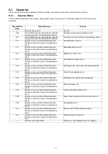
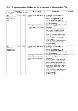
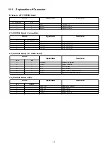
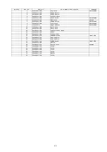
F61:
White/ Dark
calibration error
07 00 00 00 1. Power supply (+24 V) is not
properly supplied to the LED
Lamp included in the
Scanning Unit.
1. Restart the scanner, and then execute
"Carriage Drive"
in Sec. 9.3.5 to check
whether the same phenomenon is
reproduced.
2. Check the following connection and
soldering condition on each connector:
(1) JP1 (CCD Board) to LED Lamp
(2) CN1 (CCD Board) to CN2
(CONTROL Board)
(3) JP2 (CONTROL Board) to AC
Adaptor
3. Replace faulty parts.
2. The result of the calibration
is not correctly received by
the controller (ASIC on the
CONTROL).
1. Check the following connection and
soldering condition on each connector:
→
CN2 (CONTROL Board) to CN1
(CCD Board)
2. Check the soldering condition of ASIC
and its surrounding circuits on the
CONTROL Board.
3. Replace faulty parts.
3. The Scanning Unit does not
work properly.
1. Check the following connection and
soldering condition on each connector:
→
JP1 (CCD Board) to LED Lamp
2. Replace the Scanning Unit.
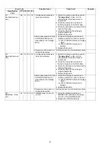
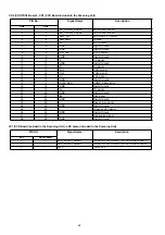
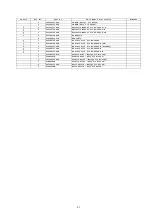
F62:
Calibration error
before scanning
image
9C 00 00 00 1. CONTROL Board does not
work properly.
1. Restart the scanner, and then execute
"Carriage Drive"
in Sec. 9.3.5 to check
whether the same phenomenon is
reproduced.
2. Check the soldering condition of ASIC,
JP5, and their surrounding circuits on
the CONTROL Board.
3. Replace the CONTROL Board.
2. The result of the calibration
is not correctly transmitted to
PC.
1. Re-connect the USB cable to the
scanner, and then restart the scanner to
confirm whether the same error occurs.
2. Replace the USB cable.
3. The power supply to the
circuit on the CONTROL
Board was interrupted.
1. Re-connect the AC Adaptor to the
scanner, and then restart the scanner to
confirm whether the same error occurs.
2. Replace the AC Adaptor.
F63:
Scanned image
error
9D 00 00 00 1. CONTROL Board does not
work properly.
1. Restart the scanner, and then execute
"Carriage Drive"
in Sec. 9.3.5 to check
whether the same phenomenon is
reproduced.
2. Check the soldering condition of ASIC,
JP5, and their surrounding circuits on
the CONTROL Board.
3. Replace the CONTROL Board.
2. The result of the calibration
is not correctly transmitted to
PC.
1. Re-connect the USB cable to the
scanner, and then restart the scanner
to confirm whether the same error
occurs.
2. Replace the USB cable.
3. The power supply to the
circuit on the CONTROL
Board was interrupted.
1. Re-connect the AC Adaptor to the
scanner, and then restart the scanner to
confirm whether the same error occurs.
2. Replace the AC Adaptor.
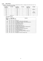
Error Code
Possible Cause
Check Point
Remarks
Classification
Code
ST1 ST2 ST3 ST4
Summary of Contents for KV-SS080
Page 7: ...7 3 COMPONENT IDENTIFICATION 3 1 Part Names ...
Page 8: ...8 3 2 Scanner Status ...
Page 15: ...15 5 SECTIONAL VIEWS 5 1 Flatbed Block and Boards ...
Page 44: ...44 11 2 Block Diagram 2 Board ...
Page 47: ...47 12 PARTS LOCATION AND MECHANICAL PARTS LIST ...
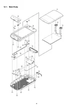
Page 48: ...48 12 1 Main Body ...
Page 50: ...50 12 2 Packing ...


