


27
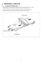
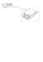
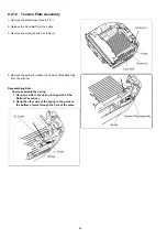
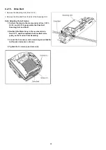
8.2.13. Shaft
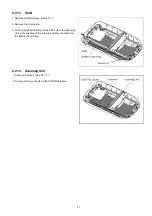
8.2.14. Scanning Unit
1. Remove the Motor Assy. (See 8.2.11.)
2. Remove the 2 screws (c).
3. Pull out the Shaft carefully through the hole in the Scanning
Unit in the direction of the arrow to separate the shaft from
the Bottom Cover Assy.
1. Remove the Shaft. (See 8.2.13.)
2. Disconnect the connector to the CONTROL Board.
Summary of Contents for KV-SS080
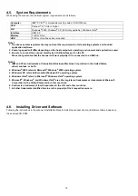
Page 7: ...7 3 COMPONENT IDENTIFICATION 3 1 Part Names ...
Page 8: ...8 3 2 Scanner Status ...
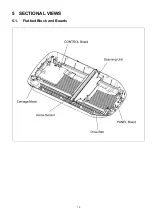
Page 15: ...15 5 SECTIONAL VIEWS 5 1 Flatbed Block and Boards ...
Page 44: ...44 11 2 Block Diagram 2 Board ...
Page 47: ...47 12 PARTS LOCATION AND MECHANICAL PARTS LIST ...
Page 48: ...48 12 1 Main Body ...
Page 50: ...50 12 2 Packing ...