


43
11 CIRCUIT DESCRIPTION
11.1. Block Diagram-1 (Image Processing)
In this system, the ASIC controls the AFE, motor, SDRAM and amplifier:
When receiving the start command from a PC, the ASIC performs some calibrations to check whether
the scanner is ready to normally scan documents by activating the CCD and Carriage Motor.
After that, the series of scanning processes start.
The CCD block will scan the pixel data (analog signals (R, G, B)) from the documents, and then transmits
the data to AFE Block through three channels: R, G, and B
The AFE Block will convert the pixel data (analog signals (R, G, B)) into the digital data.
The converted digital data is stored to the SDRAM controlled by the ASIC.
After the ASIC finishes processing the digital data according to the instructions from the PC,
the ASIC will send the processed data to the PC though the USB interface.
Summary of Contents for KV-SS080
Page 7: ...7 3 COMPONENT IDENTIFICATION 3 1 Part Names ...
Page 8: ...8 3 2 Scanner Status ...
Page 15: ...15 5 SECTIONAL VIEWS 5 1 Flatbed Block and Boards ...
Page 44: ...44 11 2 Block Diagram 2 Board ...
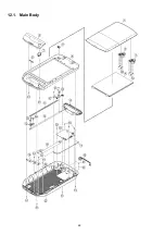
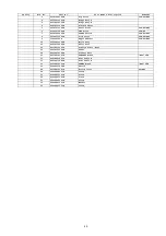
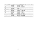
Page 47: ...47 12 PARTS LOCATION AND MECHANICAL PARTS LIST ...
Page 48: ...48 12 1 Main Body ...
Page 50: ...50 12 2 Packing ...


