background image

CHAPTER 6  RS-232C CONTROL 

6-7 


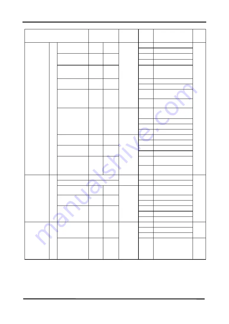
Item Command 

Selected 
Sensor 
Head (*1)

Setting 
Code 

Content Page 

0 Hold 

Analog Output 
During Alarm 

RAA WAA 

1 Fixed 

Value 

+10.9V

29.5mA 

Fixed Value 

RFM 

WFM

-10.9V

0mA 

Analog Alarm 
Delay 

RHC 

WHC

0 to F

OFF, 1, 2, 3, 4, 5, 6, 7, 
8, 9, 10, 11, 12, 13, 14, 
15 (times) 

0 OFF 

Alarm Output 
Delay 

RAC WAC

1 ON 

Operation During a 
Short Circuit 

Timing Input 
Operation 

RTM WTM

Operation During an 
Open Circuit 

Last measurement 

value  

1 Fixed 

value: 

max. 

2 Fixed 

value: 

zero 

Measurement 
value during 
timing  

RTC WTC

1/2 

3 Fixed 

value: 

min. 

0 Independent 

Input 

Input Mode 

RIM 

WIM 

1 Lump 

Input 

0 Normal 

Output Mode

 ROM 

WOM

1 Test 

Stop Emission   

During Timing 

Input/Output 21 

Laser Emission 
Control 

RTE WTE 

Continue Emission 

During Timing 

6-24 

Save MMR 

(*3) 

– 

– 

Initialize INT 

(*4) 

– 

– – 

Baud Rate 

RSA 

WSA

2 to 5

2:9600, 3:19200, 

4:38400, 5:115200 bps 

0 7 

bits 

Data Length 

RSB 

WSB

1 8 

bits 

0 Even 
1 Odd 

System 22 

Parity Check 

RSC WSC

2 None 

6-25 

0 2-head 
1 Head 

Buffering Head 
Type 

RTT 

WTT 

(*5) 

2 Head 

6-27 

Data Buffering  23 

Buffering Rate 

RBR 

WBR

(*5) 

0 to F

All, 1/2, 1/4, 1/8, 1/16, 

1/32, 1/64, 1/128, 1/256, 

1/512, 1/1024, 1/2048, 

1/4096, 1/8192, 

1/16384, 1/32768   

6-28 


Summary of Contents for HL-C1 Series

Page 1: ...ME HLC1 12 No 0031 82V Ultra High speed Laser Displacement Sensor CCD Style HL C1 series USER S MANUAL ...

Page 2: ...t Console 2 11 CHAPTER 3 INPUT AND OUTPUT TERMINAL BLOCKS 3 1 Wiring Terminal Blocks 3 1 3 2 Output Terminals 3 3 3 3 Input Terminals 3 5 3 4 Wiring Power Supply 3 7 3 5 Grounding 3 8 CHAPTER 4 MEASUREMENT 4 1 Basic Compact Console Operation 4 1 4 2 Measuring Height 4 5 4 3 Measuring Thickness 4 7 CHAPTER 5 FUNCTION ITEMS 5 1 Functions 5 1 5 2 Explanation of Functions 5 2 5 2 1 Measurement Display...

Page 3: ... 25 Calibration 5 37 Automatically Setting the Span and Shift 5 37 Direct Input of Span and Shift 5 39 About Span and Shift in Calibration and Coefficient and Offset in Calculation Formulas 5 40 5 2 26 Light Received 5 41 5 2 27 Save 5 42 5 2 28 Initialization 5 43 5 2 29 Lock 5 46 5 2 30 Communication Specification 5 47 5 2 31 Version 5 48 CHAPTER 6 RS 232C CONTROL 6 1 Communication Specification...

Page 4: ... 6 25 6 3 23 Data Buffering 6 26 6 4 List of Error Codes 6 38 CHAPTER 7 INSPECTION AND MAINTENANCE 7 1 Inspection 7 1 7 2 Maintenance 7 1 CHAPTER 8 TROUBLESHOOTING 8 1 Troubleshooting 8 1 8 2 Lock 8 2 8 3 Initialization 8 3 CHAPTER 9 SPECIFICATIONS 9 1 Sensor Head 9 1 9 1 1 Equipment Compatible to IEC 9 1 9 1 2 Equipment Compatible to FDA 9 2 9 2 Controller 9 3 9 3 Compact Console 9 5 9 4 Intended...

Page 5: ... a handling error is made This product has been developed produced for industrial use only Configure an emergency stop and interlock circuit using an external circuit Do not use this product under conditions other than those in the specifications for rating environmental conditions etc Doing so could cause abnormal heat generation or smoke emission Do not attempt to disassemble or modify this prod...

Page 6: ...age 3 5 and page 5 6 Or select Open circuit for the input operation of the timing input terminal see page 5 34 to use the terminal for a remote interlock input 4 The sensor head in this device is not equipped with a function that stops laser radiation automatically when it is disassembled so contact Panasonic Industrial Devices SUNX if it breaks down There is danger of laser radiation if the head ...

Page 7: ...3 Warning Label Laser Emission Indicator Measurement Range Indicator ...

Page 8: ...roblems to the user previously due to laser product PART1040 PERFORMANCE STANDARDS FOR LIGHT EMITTING PRODUCTS Execution standard for laser beam emitting product This standard classifies the laser product based on the level of laser danger and stipulates preventive safety measures to be executed for each class See requirements on page 7 The classification of equipment type is as follows Classifica...

Page 9: ...ntification label Label position LASER APERTURE AVOID EXPOSURE LASER RADI ATION IS EMITTED F ROM THIS APERTURE CLASS II LASER PRODUCT MAXIMUMOUTPUT1mW INTO BEAM LASER APERTURE AVOID EXPOSURE LASER RADI ATION IS EMITTED F ROM THIS APERTURE CLASS II LASER PRODUCT MAXIMUMOUTPUT1mW INTO BEAM LASER RADIATION WHEN OPEN DO NOT STARE INTO BEAM ...

Page 10: ...ensor head goes on It is also possible to recognize the LED through the laser protective glasses Laser emission indicator To attach the beam attenuator fix it with the attached screws in such a manner as to cover the light projection surface When the beam attenuator is not used fix it to either side surface of sensor head using the attached screws Beam attenuator Beam attenuator ...

Page 11: ... N A N A N A R R N A R R R 10 R N A R R R 10 R R 13 Performance specific purpose products Medical 1040 11 a Surveying leveling alignment 1040 11 b Demonstration 1040 11 c S S S S S S S S S S 8 S S S 8 NP S 11 S 8 NP S 11 Labeling all laser products Certification identification 1010 2 3 Protective housing 1040 10 g 6 7 Aperture 1040 10 g 4 Class warning 1040 10 g 1 2 3 R D 5 N A N A R R 5 N A R 6 R...

Page 12: ...l 7 CAUTION logotype 8 Requires means to measure level of laser radiation intended to irradiate the body 9 CAUTION if 2 5 mW cm 2 or less DANGER if greater than 2 5 mW cm 2 10 Delay required between indication emission 11 Variance required for Class IIIb or IV demonstration laser products and light shows 12 DANGER logotype 13 Required after August 20 1986 Export to countries overseas other than th...

Page 13: ... Avoid use in places that may be exposed to sudden temperature fluctuations causing condensation Use the sensor where luminance at the light sensor from incandescent lamps is 3 000 lx or less Power Supply Voltage The power supply voltage should be within the rated voltage range of 21 6 to 26 4V DC during use Environment If the external surge voltage exceeds 500V 1 2 50 μs unipolar full wave voltag...

Page 14: ... least 100mm apart In addition keep all signal lines as short as possible when connecting them Install this product as far away as possible from high voltage lines power lines high voltage device wireless devices and machines which generate a large starting and stopping surge If a large amount of electrical noise is generated in the power supply analog output is affected Use a noise filter or a no...

Page 15: ...instantaneous power failure is 10 to 45ms one of the following occurs 1 Operation continues 2 Analog output changes temporarily and BRIGHT and DARK indicators blink then the sensor recovers automatically 3 The same status as when the power supply is turned on occurs If an instantaneous power failure lasts more than 45ms the same status as when the power supply is turned on occurs 7 Installation Co...

Page 16: ...of the cables near to connectors Do not bend cables near connectors because this breaks wires Cables Do not pull the cable at a force more than 29 4N when routing the cable after fixing the sensor head and controller Do not allow 30mm or a shorter bending radius in the cable path During use do not bend the cable at a place within 20mm of the sensor head s cable inlet If the sensor head is to be us...

Page 17: ...ic Industrial Devices SUNX after the purchase or the delivery of the product 3 Failure caused by a development which could not be foreseen based upon the technology in practice at the time of purchase or contract 4 Failure caused by use which deviates from the conditions environment given in the product catalog or specifications 5 In case this product is used by being incorporated in the customer ...

Page 18: ...CHAPTER 1 NAMES AND FUNCTIONS OF PARTS ...

Page 19: ... Laser Emission Indicator Green 2 BRIGHT Indicator Red 3 DARK Indicator Red 4 Not used 5 COM Port 6 Connector for Compact Console 7 Not used 8 Sensor Head 1 Connector 9 Sensor Head 2 Connector 13 DIN Rail Mounting Hook AL1 O11 O12 AL2 O21 O22 V1 I 1 V2 I 2 I 11 I 12 TM1 TM2 I 21 I 22 GND GND NOT USE COM NOT USE HEAD 1 HEAD 2 LASER BRIGHT DARK ...

Page 20: ...nector for Compact Console This enables measurement values to be displayed using the compact console and connection of the compact console exclusive connection cable when setting each setting 7 Not used This port is for adjustment at the factory before shipping 8 Sensor Head 1 Connector The controller operates the sensor head connected to this connector as sensor head 1 9 Sensor Head 2 Connector T...

Page 21: ...CHAPTER 1 NAMES AND FUNCTIONS OF PARTS 1 3 1 2 Sensor Head 1 Laser Emission Indicator Green 2 Measurement Range Indicator Yellow 3 Warning Label ...

Page 22: ...surement Range Indicator Yellow Blinks when within the measurement range and lights when near the center of the measurement range 3 Warning Label Shows the laser emission position Note description contents 4 Light Receiver Receives light reflected from the measured object 5 Light Emitter Emits laser light 5 Light Emitter 4 Light Receiver Connector ...

Page 23: ... AND FUNCTIONS OF PARTS 1 5 1 3 Compact Console 1 Liquid Crystal Panel Touch Panel 2 Front Protective Sheet Front Rear 6 Waterproof Packing 3 Power Supply Terminal COM Port 4 TOOL Port 5 Operating Mode Setting Switch ...

Page 24: ...used for connecting the compact console to the controller using the exclusive cable provided with the console 4 TOOL Port The TOOL port is used to create screen data with the product connected to a personal computer Do not use the port for this equipment equipment has already been incorporated with dedicated screen data 5 Operating Mode Setting Switch Use this product in the status below to protec...

Page 25: ...CHAPTER 1 NAMES AND FUNCTIONS OF PARTS 1 7 MEMO ...

Page 26: ...CHAPTER 2 INSTALLATION ...

Page 27: ...head 1 HEAD 1 connector Controller RS 232C Cable 3m Supplied with the intelligent monitor HL C1AiM Connection Cable 2m supplied with the compact console Extension Cable 2m 5m 10m 20m 30m Sensor Head Compact Console AL1 O11 O12 AL2 O21 O22 V1 I 1 V2 I 2 I 11 I 12 TM1 TM2 I 21 I 22 GND GND NOT USE COM NOT USE HEAD 1 HEAD 2 LASER BRIGHT DARK ...

Page 28: ...pment Do not let excessive static electric charges be applied to the panel surface since it could destroy the LCD unit Heat Radiation Considerations Do not mount this product on a heater transformer or other device that radiates large amounts of heat such as high capacity resistors If the controller is mounted internally on a control board where air circulation is blocked ambient temperature will ...

Page 29: ...oller to fasten it on the rail Removal 1 Insert the blade of a flat bladed screwdriver in the mounting lever 2 Pull down the mounting lever 3 Raise the controller and remove it from the rail Mounting the Controller with Screws While referencing the external dimensioned diagram on page 10 6 use M3 screws to fasten the controller Do not tighten screws beyond 0 5N m To avoid breakage inside the contr...

Page 30: ...g contents If the power supply is turned on with the connection changed change in equipment type 50mm 85mm change in connection from 1 sensor head to 2 sensor head or vice versa from that when controller setting contents are saved setting contents are initialized If the connection is incorrect turn off the power supply to return the connection to that when the controller setting was saved then tur...

Page 31: ...scent lamps is 3 000lx or less Mount the sensor head so stray light such as sunlight or light with the same wavelength etc does not enter the light receiver Where accuracy is a factor use with a shading plate etc Do not mount the sensor head where flammable or corrosive gases are generated dust is excessive water drips exposure to direct sunlight is possible or severe vibrations or impacts occur I...

Page 32: ...CHAPTER 2 INSTALLATION 2 6 z Measurement of specular reflection 50mm type 85mm type ...

Page 33: ...Head Mounting Direction Mount the sensor head in the orientation shown below to ensure accurate measurement z Rotating objects z Objects with level differences or grooves z Objects with great changes in color Good Good Not good Not good ...

Page 34: ...if the neighboring sensor s laser spot is outside the shaded portion in the figure below Mount other sensor heads so laser spots do not enter the shaded area When using 2 sensor heads connected to 1 controller it is possible to use the interference prevention function Refer to 5 2 12 Interference Prevention 50mm type 85mm type Unit mm ...

Page 35: ...fused reflection Analog output is set to initial status Measurement Range Measurement Center Dist 50mm type 85mm type Unit mm 50mm type 85mm type Measurement Range Indicator Lights Off Blinks Distance mm Displacement Output Measurement Center Dist Measurement Range Alarm Output N C Open Closed Off Blinks 5 20 5V 5 20 ...

Page 36: ... of specular reflection Analog output is set to initial status Measurement Range Indicator Off Distance mm Displacement Output Measurement Center Dist Measurement Range Alarm Output N C Open Closed 50mm type 85mm type Lights Blinks Blinks Off ...

Page 37: ...witches Tighten screws with a torque of 0 1 to 0 25N m Use a panel 1 0 to 5 0mm thick Clearances During Mounting When mounting the compact console if other parts are on the panel and wiring is required it is recommended that a clearance of 30 to 50mm be allowed around the compact console to prevent damage to cables improve workability etc Do not cover slits in the console unit Wiring the Connectio...

Page 38: ...V DC during use Tighten screws on the terminal block with a torque of 0 22 to 0 25N m Force exceeding this may damage the device If compression terminals are not used use wire 0 5 to 1 25mm 2 in diameter To comply with the European EMC Directive install a ferrite core Seiwa Electric Mfg Co Ltd E04RC281613 or equivalent on wires to the terminal block as shown below Separate wiring to the compact co...

Page 39: ...CHAPTER 2 INSTALLATION 2 13 MEMO ...

Page 40: ...CHAPTER 3 INPUT AND OUTPUT TERMINAL BLOCKS ...

Page 41: ...inal Block Socket Phoenix Contact Co Ltd MC1 5 16 ST 3 5 Color Green Flat blade screwdriver Tightening Torque Tightening Tool Blade size 0 4 2 5 0 22 to 0 25N m Size Conductor Cross Section Applicable Wire twisted wire AWG 24 to 16 0 3 to 1 25mm 2 Input Power Supply Terminal Block Output Terminal Block AL1 O11 O12 AL2 O21 O22 V1 I 1 V2 I 2 I 11 I 12 TM1 TM2 I 21 I 22 GND GND N OT USE COM N OT USE ...

Page 42: ...ot use wires tinned with solder They may break when subjected to vibration Wiring to the terminal block must not exceed 30m 1 Strip insulation from the end of the wire 3 If more than 1 wire is inserted into the same terminal twist wires before inserting them 2 Insert the wire in the terminal block until it contacts the back then secure it by tightening the screw ...

Page 43: ...Sensor Head 2 GND Analog Output Ground NPN output Symbol Meaning AL1 Alarm Output Sensor Head 1 O11 Judgment Output 1 Sensor Head 1 O12 Judgment Output 2 Sensor Head 1 COM Output Common AL2 Alarm Output Sensor Head 2 O21 Judgment Output 1 Sensor Head 2 O22 Judgment Output 2 Sensor Head 2 COM Output Common Not used Not used V1 Analog Voltage Output Sensor Head 1 I1 Analog Current Output Sensor Head...

Page 44: ...onds after turning on the power supply until the operation condition is ensured completion of start up when the moving average count is turned off and interference prevention function is turned off This start up time is increased by setting the moving average count or by turning on the interference prevention function It is increased 1 2 to 2 4 times when the maximum moving average count is 32 768...

Page 45: ... Power Supply Power Supply Ground Function Ground NPN output Symbol Meaning TM1 Timing Input Sensor Head 1 I11 Zero Set ON Input Sensor Head 1 I12 Zero Set OFF Input Sensor Head 1 COM Input Common TM2 Timing Input Sensor Head 2 I21 Zero Set ON Input Sensor Head 2 I22 Zero Set OFF Input Sensor Head 2 COM Input Common Not Used Not Used Not Used Not Used Not Used 24V DC Input for Power Supply Power S...

Page 46: ...Allow 2ms or more interval between the inputs Add Zero Set ON input only when the sensor head is within the measurement range If lump input mode is selected see page 5 36 add timing input Zero Set ON input and Zero Set OFF input at either the sensor head 1 or sensor head 2 input terminal NPN output Photoelectric Sensor etc Laser Sensor Internal Circuit Photo MOS output Operating input voltage 12 t...

Page 47: ...tor If a power supply without an internal protective circuit is used supply power to the controller via a protective element such as a fuse Switch the Power Supply On and Off at the Primary Side Switch the power supply on and off at the primary side 100V AC If it is switched on and off at the secondary side 24V DC the controller s fuse may burn out To Improve Noise Resistance Wire the controller i...

Page 48: ...45ms one of the following occurs 1 Operation continues 2 Analog output varies temporarily and BRIGHT and DARK indicators blink then the sensor recovers automatically 3 The state changes to reset If an instantaneous power failure lasts more than 45ms the state changes to reset Use This Product Correctly When wiring the power supply turn the power supply off 3 5 Grounding Grounding When Effects of N...

Page 49: ...CHAPTER 3 INPUT AND OUTPUT TERMINAL BLOCKS 3 9 MEMO ...

Page 50: ...CHAPTER 4 MEASUREMENT ...

Page 51: ...he average number of samples high pass filters and low pass filter Input Output Used to select the input or output function and set upper and lower limit values etc System Saves or initializes setting contents locks screens sets the communication specification displays the screen version etc Shifting Screen Levels Touching item keys on the MENU screen changes the screen to respective operating scr...

Page 52: ...er and lower limit or offset etc A keyboard is displayed for items that can be input 1 Touch the frame above the setting value to change the mode to the number input mode and causes the cursor to blink 2 Input the number from the keyboard 3 Touch the decimal point on the keyboard to input decimal fractions 4 Touch the enter key to make the setting Caution Before connecting the compact console and ...

Page 53: ...CHAPTER 4 MEASUREMENT Screen Flow 4 3 Measurement Sensor Adjust ment System Input Output Data Processing Measurement Setting 1 2 4 5 3 6 ...

Page 54: ...CHAPTER 4 MEASUREMENT 4 4 1 2 4 6 3 5 ...

Page 55: ...ent value is displayed on the compact console 3 Adjust the position of the sensor head Set the orientation of the measurement object and the sensor head referencing Mounting the Sensor Head on page 2 4 While observing the measurement range indicator yellow of the sensor head or measurement display on the compact console adjust the mounting position of the sensor head so the approximate measure men...

Page 56: ...easure the measurement item s surface z Supplementary Explanation If deviation in measurement occurs due to the status of the measurement object s surface set the calibration referring to see Calibration on 5 37 If the sampling period page 5 8 average number of samples page 5 20 and digital filter pages 5 21 22 are changed to correspond to the measurement object s speed of movement displacement an...

Page 57: ...rientation of the measurement object and the sensor heads referencing Mounting the Sensor Head on page 2 4 While observing the measurement range indicator yellow of the sensor head or measurement display on the compact console adjust the mounting position of the sensor head so the approximate measurement center is in the center of the measurement object s variation range The measurement range indi...

Page 58: ...en display the Add subtract Calculation Screen Touch the Calculation Formula key and display 6 Display the actual thickness On the subscreen the next level below the Add Subtract Calculation screen touch the key input the offset value L using a value enabling the actual measurement value to be displayed on the measurement value display see page 5 12 The L input range is 999 999mm After the setting...

Page 59: ...en touch and make a zero setting z Supplementary Explanation When deviation occurs in measurement value based on the surface status of the object execute calibration referencing page 5 37 Changing the sampling cycle page 5 8 moving average count page 5 20 and digital filter pages 5 21 22 based on the speed of movement displacement ratio and displacement contents of object substance ensure furtherm...

Page 60: ...CHAPTER 5 FUNCTION ITEMS ...

Page 61: ...to a large number to assure a stabilized measurement value 5 20 Low Pass Filter Changes the cutoff frequency of the low pass filter to avoid the influence of steep changes 5 21 High Pass Filter Changes the cutoff frequency of the high pass filter to avoid the influence of gentle changes 5 22 Data Processing Simplified optical filter Reduces the influence due to turbulence of the reflected light on...

Page 62: ...judgment output screen In output status the output symbols are displayed in reverse highlighting In nonoutput status the output symbol is not displayed H1 and H2 correspond to output on the terminal block For independent operation judgment outputs 01 02 of H1 are used for Sensor Head 1 For addition subtraction such outputs are used for addition subtraction There is a corresponsing alarm output AL ...

Page 63: ...Outputs the displacement from the measurement center in real time Standard setting P P This mode holds and output the difference between maximum and minimum values Used for vibration measurement or eccentricity PEAK Holds and outputs the maximum measurement VALLEY Holds and outputs the minimum measurement Output Changes in Hold Modes NORM PEAK P P VALLEY ...

Page 64: ...nd specular reflection mode are changed Do not change the hold mode if the object being measured is outside the measurement range Otherwise the correct measurement may not be displayed If display hold see page 5 7 is set the measurement displayed at timing is maintained and the measurement displayed on the compact console does not change Analog output judgment output and other output are issued ba...

Page 65: ... H1 Sensor Head 1 H2 Sensor Head 2 In add subtract operation the analog output of sensor head 1 and sensor head 2 becomes 0 In the zero set state is displayed in reverse highlighting Zero Set is canceled if the Zero Set key is touched again Cancel zero setting to return the reference position of measurement to the center of measurement default Zero set is canceled if the hold mode is changed Chang...

Page 66: ...al input has priority Laser emission can be halted or continued while timing is being input so that timing can be used as laser emission control While timing is being input the measuring range indicator of the sensor head is unlit regardless of the laser emission setting halt or continue See page 5 34 When timing input is interrupted during the laser emission halt setting the alarm output is activ...

Page 67: ... the subscreen by touching 2 If is touched measurement is held Analog output judgment output and alarm output are not held During independent operation this operation is executed for each sensor head H1 Sensor Head 1 H2 Sensor Head 2 is displayed in reverse highlighting when in the hold state Touching again cancels the hold state Data is not stored in memory even if save is executed Reference Defa...

Page 68: ...surement setting screen Touch on the MENU Screen The screen changes to the measurement setting screen Touch the The screen changes to the measurement condition screen and the currently set sampling period is displayed 2 Display the optimum sampling period using the Sampling Period key The sampling period is set for the 2 sensor heads in common so it cannot be set for each sensor head Each time the...

Page 69: ...n in shortest sampling period operation with 2 sensor heads Shortest sampling 100µs 144µs 200µs Specular reflection mode Standard Front Rear Thickness Optical filter OFF ON 3 OFF ON 4 Emission adjustment Auto Fixed 3 Auto Fixed 4 Data buffering OFF 1 ON 2 3 1 Normal measurement non buffering mode selected 2 Buffering mode selected 3 The sampling period is set to 144µs when either is selected 4 The...

Page 70: ... the MENU screen by touching change the screen to the measurement display screen by touching Reference Default setting Ind Independent z Supplementary Explanation The measurement display screen shows that corresponding to independent or add subtract head operation mode Change from to to output the result of addition or subtraction to sensor head 1 i e the the result of sensor head 2 being added or...

Page 71: ...urement to a value the customer wishes to assign as the standard value K Used in special cases such as changing the degree of fluctuation between the 2 sensor heads Ordinarily it is 1 1 Display the measurement setting screen Touch on the MENU Screen The screen changes to the measurement setting screen Touch the The screen changes to the measurement condition screen and the sampling period currentl...

Page 72: ...nt operation touch and set the Offset L and coefficient K for each sensor head H1 Sensor Head 1 H2 Sensor Head 2 Reference Input Range L1 L2 L 999 9999mm K1 K2 K 0 0001 to 99 9999 Default Settings L1 L2 L 0 K1 K2 K 1 z Supplementary Explanation A and B in the calculation formula for the add subtract mode indicate results of independent calculation of sensor head 1 and sensor head 2 For example L K...

Page 73: ...to the measurement setting screen Touch and display the measurement condition screen 2 Touch 3 times and display the emission adjustment screen When is touched 3 times on the measure ment condition screen the current selection status is displayed 3 Adjust the emission amount using the select key Touch Emit adj key to adjust emission The display changes as shown below each time the key is touched R...

Page 74: ...s to the measurement setting screen Touch The screen changes to the measurement type screen and the measurement mode currently set is displayed 2 Change measurement mode using the Measurement Mode key Change the measurement mode for each sensor head H1 sensor head 1 H2 sensor head 2 to change the screen as below each time the key is touched For diffused reflection do not attempt to change the meas...

Page 75: ...age 5 23 is set to ON When measurement mode is changed from Specular reflection to Diffused reflection the Emission Adjustment is changed to Auto automatically even if Emit adj is set to Fix Note The default setting will not be linked with the change of the measurement mode For the default setting the upper limit lower limit and analog output settings have been preset to the contents of Diffused r...

Page 76: ... is Diffused reflection change it to Specular reflection referring to the description on the previous page 2 Select specular reflection mode using the Specular Reflection Mode key Select specular reflection mode based on the measurement object for each sensor head H1 sensor head 1 H2 sensor head 2 The display is changed as below each time the key is touched When the Thk Thickness is selected for c...

Page 77: ...ness For general sheet glass guideline measurement objects are as follows although it may depend upon other conditions such as refractive index 50mm specular reflection Thickness of 0 5mm or more 85mm specular reflection Thickness of 1 2mm or more Conduct measurement with values both for surface and back within the measurement range For luminous energy feedback See Emission Adjustment on page 5 13...

Page 78: ...the interference prevention function is enabled It is turned on off each time the key is touched 3 The screen returns to the MENU screen when is touched and to the Measurement Setting screen when is touched Touch to return the screen to the MENU screen or to change to the measurement setting screen Reference Default setting OFF z Supplementary Explanation Do not set the Interference Prevention key...

Page 79: ... touched 3 The screen returns to the MENU screen when is touched and to the measurement setting screen when is touched Touch to return the screen to the MENU screen or to change to the measurement setting screen Reference Default setting OFF z Supplementary Explanation In the laser emission delay OFF condition in case the timing input is canceled under Zero set state an incorrect measurement value...

Page 80: ...mples key 2 Display the optimum average number of samples using the Average Number of Samples key Set the average number of samples to each sensor head H1 Sensor head 1 H2 Sensor head 2 The display changes as below each time the key is touched To execute moving average processing it takes the time of Sampling period Average number of samples until measurement is stabilized 3 The screen returns to ...

Page 81: ... Pass High Pass screen Cutoff frequencies currently set are displayed 2 Display the optimum cutoff frequency using the Low Pass key Set the frequency for each sensor head H1 Sensor Head 1 H2 Sensor Head 2 Each time the key is touched the display value changes in the sequence below 3 The screen returns to the MENU screen when is touched and to the data Processing screen when is touched Reference De...

Page 82: ...he screen returns to the MENU screen when is touched and to the data Processing screen when is touched Reference Default Setting OFF z Supplementary Explanation Set the cutoff frequency of the high pass filter to a value smaller than the cutoff frequency of the low pass filter In case the timing input is also used with this function laser emission in the timing input ON state should be set to LD e...

Page 83: ...Filter key 2 Turn on the display using the Optical Filter key When the display is turned on the optical filter function is enabled It is turned on off each time the key is touched When the optical filter function is enabled measurement is offset probably resulting in deviation from the line of measurement Calibrate measurement before use For operation with 2 sensor heads connected the shortest sam...

Page 84: ...t operation This setting value is the same for to all hold modes See page 4 2 for keyboard input 3 Display the lower limit value screen From the upper limit value screen touch to go to the lower limit screen The current setting value and a keyboard for inputting numbers are displayed The lower limit value is the lower limit for sensor head 1 in independent operation and the lower limit for the add...

Page 85: ... Setting Set hysteresis for upper and lower limit values to prevent chattering Because the resolution changes based on the workpiece measured the average number of samples and so on set operating conditions and use the P P mode to obtain an estimated resolution before setting hysteresis Hysteresis can be set for each sensor head 1 Display the upper limit hysteresis screen from the input output scr...

Page 86: ...hip between the set hysteresis value and activation and deactivation of output is shown at the right Hysteresis works evenly i e the value of each regarding the upper or lower limit values Output ON active output indicates an open terminal Reference Input range Upper or lower limit hysteresis 0 0000mm to 2 0000mm Input an even number for the least significant digit Default setting Upper or lower l...

Page 87: ... Output Type Key Input output Screen MENU Screen Select to distinguish between the upper limit and lower limit when the measurement value exceeds either limit Select to distinguish between deviation from the upper or lower limit value and containment in the range Use this for OK NG judgment Select to distinguish whether the measurement value is below the lower limit value above the upper limit val...

Page 88: ...creen Touch on the input output screen and display the judgment select screen Display Test using the output mode key When Test is selected the output becomes proportional to the light received without relation to upper and lower limit settings Do not make inadvertent changes Under normal conditions return to and use as is This setting is common to sensor head 1 and sensor head 2 Reference Default ...

Page 89: ...creen 3 Display the output setting screen Touch on the analog output screen The current measurement setting corresponding to 5V 20mA and a keyboard for inputting numbers are displayed The value is for sensor head 1 H1 in independent operation and it is the value corresponding to the add subtract calculation value AS ADD SUB in add subtract operation 4 Set measurement which 5V is to correspond to S...

Page 90: ...to 5V 4mA for sensor head 2 8 Return to the MENU screen using or to analog output screen by touching or the input output screen by touching again Reference Input Range 5V Value 5V Value 999 9999mm Default Settings Sensor Head 1 5V Value Add subtract Calculation Value 5V Value 5 0000mm 20 0000mm Sensor Head 1 5V Value Add subtract Calculation Value 5V Value 5 0000mm 20 0000mm Sensor Head 2 5V Value...

Page 91: ... output screen Touch on the input output screen and display the analog output screen 3 Display the analog output during alarm screen If is touched on the analog output screen the currently selected status is displayed To change the setting touch the Select key Select one of the following settings Hold 4 Select the content of the fixed value If selecting a fixed value it is possible to select outpu...

Page 92: ... output screen 2 Display analog output during alarm screen Touch on the input output screen Touch to display analog output during alarm screen 3 Touch on the analog output during alarm screen to display the analog alarm delay screen Using the delay key set the number of updating times for data to delay analog alarm output fixed output The display changes as shown below each time the key is touched...

Page 93: ...eturn to the input output screen Reference Default Setting Analog alarm delay OFF Alarm delay OFF z Supplementary Explanation Number of times here means the number of times data is updated normally 1 time sampling period When Interference prevention is set it is 1 time per 4 sampling periods ...

Page 94: ...y is touched the selection switches back and forth between the two selections below Short ckt Open Reference Default Setting During Short Circuit z Supplementary Explanation The zero set ON input and zero set OFF input are always valid upon a short circuit without relation to the setting LD Emission To continue laser emission without interruption even during timing input change it here 1 Display t...

Page 95: ...ay the Input output screen Then touch on the input output screen and display the timing input screen 2 Display the measurement value during timing input screen Touch on timing input screen and display the measurement value during timing input screen 3 Set the value to be held Select the setting on each sensor head H1 Sensor head 1 H2 Sensor head 2 Each time the key is touched the display changes a...

Page 96: ...ctions below Ind I P Lump I P Reference Default Setting Ind I P Independent Input z Supplementary Explanation This setting is valid for timing input zero set ON input and zero set OFF input If the type of operation is switched from independent operation to add subtract operation the input switches automatically to Lump Input To switch back to independent operation from add subtract operation it re...

Page 97: ...ically Setting the Span and Shift In automatic calibration mode designate the start and end points to set the offset Shift and span are automatically determined so the start point becomes 0 and the end point becomes the offset 1 Display the Calibration screen Touch on the MENU Screen then touch on the sensor adjustment screen to display the Calibration screen 2 Select the sensor head to be calibra...

Page 98: ...ation screen Reference Default Setting Span 1 0000 Shift 0 0000mm Input range Span 0 9000 to 1 1000 Shift 99 9999mm See the next page on direct input methods steps 1 2 and 4 for checking and changing calibration setting values span shift z Supplementary Explanation During automatic calibration span or shift exceeding the input range is forcibly adjusted to the maximum or minimum value After finish...

Page 99: ...to the span screen and the current span setting together with a keyboard for inputting numbers is displayed 3 Input the span See page 4 2 for keyboard input 4 Input the shift Touching in the span screen causes the currently set shift value and a keyboard for inputting numbers to be displayed so if necessary input the shift value 5 Return by touching either or Return to the MENU screen by touching ...

Page 100: ...measurement for actual displacement is great or small Ordinarily this setting is left at its initial setting 1 The calibration shift is for correcting deviation in measurement its input range is 99 9999mm In contrast calculation formula offset is used to increase or decrease the value to display actual dimensions so its input range is wider 999 9999mm The same effect is obtained by using either se...

Page 101: ... the DARK state occurs If the value is greater than 1 023 light received is excessive and the BRIGHT state occurs 3 Touch or to return Touch to return to the MENU screen and touch to return to the sensor adjustment screen z Supplementary Explanation The light received for the surface reflection beam is displayed for the light received Note that light received from the back surface reflection beam ...

Page 102: ...pleted the screen changes to the end screen so touch to return to the MENU screen Do not turn the power off until the screen changes to the end screen If power is turned off before that it could result in data being destroyed and the system being unable to start normally so exercise caution z Supplementary Explanation Timing input state and display hold state are not saved Notes When the power sup...

Page 103: ...s to the end screen When initialization is completed the screen changes to the end screen Return to the MENU screen by touching Do not turn power off until the screen changes to the end screen If power is turned off before that it could result in data being destroyed and the system being unable to start normally so exercise caution See default values on page 5 44 for their content z Supplementary ...

Page 104: ...Upper Limit Value 5 0000mm 20 0000mm Lower Limit Setting Lower Limit Value 5 0000mm 20 0000mm 5 24 Hysteresis Setting Upper Limit Hysteresis 0 0100mm 0 0300mm Hysteresis Setting Lower Limit Hysteresis 0 0100mm 0 0300mm 5 25 Judgment Output Selection LOW HIGH 5 27 Output Mode Normal 5 28 Analog Output Setting 5V Value 5 0000mm 20 0000mm Analog Output Setting 5V Value 5 0000mm 20 0000mm 5 29 Analog ...

Page 105: ...PTER 5 FUNCTION ITEMS 5 45 1 Initial value Head type Hysteresis setting Upper limit hysteresis Lower limit hysteresis 50mm 0 0100mm 85mm 0 0300mm 107mm 0 0300mm 210mm 0 1000mm 320mm 0 3000mm 350mm 0 3000mm ...

Page 106: ...e save 1 Display the system screen Touch on the MENU Screen to display the system screen 2 Touch to display the lock screen The current state is displayed in reverse highlighting To set the console in the locked state touch To release the locked state touch This causes the key to be shown in reverse highlighting The screen can be changed even in the locked state so setting values can be displayed ...

Page 107: ... display changes as shown below each time the key is touched 4 Touch or key to return to the MENU Screen and the system screen Reference Default Setting Baud rate 115 200bps Parity check None Data length 8 bits z Supplementary Explanation If the communication specification settings e g baud rate parity check or data length must be changed save the settings after the change turn off controller powe...

Page 108: ... on the system screen the screen changes to the version screen The version of the controller that is displayed is the same version as the rating nameplate attached to the side of the controller The version displayed at the console is the same as that specified on the ratings nameplate on the back of the operation screen of the compact console 3 Return to the previous screen by touching MENU Screen...

Page 109: ...CHAPTER 5 FUNCTION ITEMS 5 49 MEMO ...

Page 110: ...CHAPTER 6 RS 232C CONTROL ...

Page 111: ...Parity Check Even Odd None Stop Bit Length 1 bit End Code CR 0DH BCC Yes 1 1 To omit BCC calculation enter 2AH 2AH as BCC 2 Underlining indicates the default status at shipment from the factory Pin Arrangement Controller side Pin No I O Signal Name 1 OUT SD TXD 2 IN RD RXD 3 OUT RS RTS 4 IN CS CTS 5 IN DR DSR 6 SG GND 7 IN CD DCD 8 OUT ER DTR z Compatible Connector Reference Hoshiden TCP6180 Conne...

Page 112: ... table of communication specifications on page 6 1 set specifications based on customer application status z Set personal computer communication specifications For personal computer RS 232C communication specifications read the manuals on the personal computer etc before setting them to the same values as those for the controller z Supplementary Explanation When the communication settings content ...

Page 113: ...rning on the power supply Note that sending Commands continuously during start up may slow start up Data Transmission Format The transmission format of Commands and data sent from the PC to the controller is shown below Only uppercase letters are used 1 Read settings 2 Change settings 3 Set a number E E W Select Head 1 to 3 Setting Code 0 to F Command dependent Setting Command Code R C BCC Command...

Page 114: ...to cause the automatic period change to occur due to a restriction see page 5 9 ofin the shortest sampling period is sent 2 When it is an initial Command response after occurrence ofan automatic period change occurs using the compact console For Error shown in item 4 the data format is not substituted for Setting Command Code E E W R C BCC Response Symbol E E R Setting Command Code Response Symbol...

Page 115: ...Output 1 ROB 1 Judgment output 1 is in output state 0 Judgment output 2 is in non output state 2 Read Judgment Output 2 ROC 1 Judgment output 2 is in output state 6 9 0 NORM 1 P P 2 PEAK 3 Hold Mode RHM WHM 3 VALLEY 6 11 0 OFF Zero Set RZS WZS 1 ON 0 OFF Measurement 4 Timing RTI WTI 1 2 1 ON 6 11 0 1 000µs 1 498µs 2 332µs 3 255µs 4 200µs 5 144µs 5 Sampling Period RSP WSP 2 6 100µs 6 12 0 Independe...

Page 116: ... Emission Delay RLE WLE 1 ON 6 17 0 OFF Measurement setting 13 Interference Prevention RXT WXT 3 1 ON 6 17 Span RCL WCL 0 9000 to 1 1000 Sensor Adjustment 14 Shift ROF WOF 1 2 99 9999mm 6 18 15 Average RAV WAV 0 to F OFF 2 4 8 16 32 64 128 256 512 1024 2048 4096 8192 16384 32768 times 6 18 Low Pass Filter RLP WLP 16 High Pass Filter RHP WHP 0 to 8 OFF 10 20 50 100 200 500 1000 2000 Hz 6 19 0 OFF D...

Page 117: ...ue zero Measurement value during timing RTC WTC 1 2 3 Fixed value min 0 Independent Input Input Mode RIM WIM 1 Lump Input 0 Normal Output Mode ROM WOM 1 Test 0 Stop Emission During Timing Input Output 21 Laser Emission Control RTE WTE 3 1 Continue Emission During Timing 6 24 Save MMR 3 Initialize INT 4 Baud Rate RSA WSA 2 to 5 2 9600 3 19200 4 38400 5 115200 bps 0 7 bits Data Length RSB WSB 1 8 bi...

Page 118: ...Initial trigger 3 Updated trigger 4 Timing trigger Buffering Mode RBD WBD 5 3 5 Updated continuous 6 33 Stop WCB 5 1 Buffering accumulation stops 6 34 Status Reading RTS 5 Read once Final Data Point RLD Read once 6 35 RLA Normal reading Data Buffering 23 Data Reading RLB 1 2 High speed reading 6 36 1 For sensor head selection see Select Sensor Head on page 6 4 2 3 4 5 Transmission wait time When t...

Page 119: ...ted 6 3 2 Read Alarm Output Read Judgment Output Command Code Function Read Setting code Content 0 Alarm not output state 1 Measurement alarm output state 2 Head memory error 3 Controller memory error 4 Head Controller memory error Read Alarm Output ROA 5 Sensor head are unconnected Both heads 0 Judgment output 1 non output state Read Judgment Output 1 ROB 1 Judgment output 1 output state 0 Judgme...

Page 120: ...after the setting was saved and the unit was re started Even if either of the selected sensor head 1 or 2 is read this alarm is reflected Code 4 The head memory error and the controller memory error occurred at the same time Code 5 Both of the sensor head 1 and 2 are not connected Even if either of the selected sensor head 1 or 2 is read this alarm is reflected Example 1 Read alarm output state sh...

Page 121: ...de Content 0 OFF Zero Set RZS WZS 1 ON 0 OFF Timing RTI WTI 1 ON Example 1 Read setting content shown with BCC omitted If sensor head 1 is in the zero set state 2 Change the setting shown with BCC omitted Timing is turned ON for sensor head 2 Setting Code BCC Select Head Command Code E R H M E C R BCC Command Code W H M E E C R Select Head W H M E E C R E E W H M 2 1 C R E E R H M 1 C R R H M E E ...

Page 122: ... Add subtract operation Example 1 Read setting content shown with BCC omitted If the sensor head operation is independent operation 2 Change the setting shown with BCC omitted Set the sensor head operation on add subtract operation In add subtract operation sensor head 1 setting content becomes the setting in add subtract operation BCC Select Head Command Code E R S P 3 E C R BCC Setting Code Comm...

Page 123: ...NT 3 L K A B Example 1 Read setting content shown with BCC omitted If sensor head 2 calculation formula is L KA 2 Change the setting shown with BCC omitted Change the add subtract calculation formula to L K A B W N T E E C R E E W N T 3 3 C R E E R M T 2 C R R M T E E 1 C R Send Respond Setting Code BCC Command Code W N T 3 E E C R Select Head Setting Code Command Code W M T E E BCC C R Select Hea...

Page 124: ...CC omitted If sensor head 1 calculation offset is 5 1200mm 2 Change the setting shown with BCC omitted Set the add subtract calculation coefficient to 1 5000 z As for selecting the sensor head see page 6 4 Select Sensor Head BCC Select Head Command Code E R M E C R Setting Code Command Code W M E E BCC C R Select Head BCC Select Head Command Code E R N 3 E C R Setting Code Command Code W N 3 E E B...

Page 125: ...ustment RFB WFB 7 25 Example 1 Read the setting content shown with BCC omitted When the emission adjustment of Sensor Head 1 is selected to Auto 2 Change the setting shown with BCC omitted Set the emission adjustment of Sensor Head 2 to 10 fix E E W Select Head Setting Code Command Code F B R C BCC Command Code R E E B F Select Head R C BCC E E R C F B R 1 Send E E R F B R C 0 Respond E E W R C F ...

Page 126: ...ontent 0 Front 1 Rear 2 Thickness Specular Reflection Mode RSM WSM 3 Standard Example 1 Read setting content shown with BCC omitted When the specular reflection mode of sensor head 1 is set to Thickness 2 Change the setting shown with BCC omitted Select the specular reflection mode of sensor head 2 to Front W M M E E C R E E W M M 2 1 C R E E R M M 1 C R R M M E E 0 C R Send Respond Setting Code B...

Page 127: ...etting Code Content 0 OFF Interference Prevention RXT WXT 1 ON Example 1 Read setting content shown with BCC omitted When the Interference Prevention mode is not set 2 Change the setting shown with BCC omitted Set the Interference Prevention mode W L E E E C R E E W L E 3 1 C R E E R L E 3 C R R L E E E 0 C R Send Respond Setting Code BCC Select Head Command Code E R X T 3 E C R BCC Command Code W...

Page 128: ...ting shown with BCC omitted Set sensor head 1 shift to 12 3456mm 6 3 15 Average Command Code Function Read Set Setting Code Content Setting Code Content 0 OFF 8 256 times 1 2 times 9 512 times 2 4 times A 1 024 times 3 8 times B 2 048 times 4 16 times C 4 096 times 5 32 times D 8 192 times 6 64 times E 16 384 times Average RAV WAV 7 128 times F 32 768 times Setting Code Command Code W E E BCC C R ...

Page 129: ...000Hz High Pass Filter RHP WHP 8 2 000Hz Example 1 Read setting content shown with BCC omitted If sensor head 1 low pass filter s cutoff frequency is 50Hz 2 Change the setting shown with BCC omitted Set sensor head 2 high pass filter cutoff frequency at to 500Hz BCC Select Head Command Code E R A V E C R BCC Setting Code Command Code W A V E E C R Select Head W A V E E C R E E W A V 2 0 C R E E R ...

Page 130: ...le 1 Read setting content shown with BCC omitted When the optical filter of sensor head 1 is turned off 2 Change the setting shown with BCC omitted Turn on the optical filter of sensor head 2 Setting Code BCC Select Head Command Code E R C M E C R BCC Command Code W C M E E C R Select Head W C M E E C R E E W C M 2 1 C R E E R C M 1 C R R C M E E 0 C R Send Respond ...

Page 131: ...ead 2 lower limit value to 98 7654mm 3 Read the setting shown with BCC omitted For an upper limit hysteresis of sensor head 2 of 0 0050mm 4 Change the setting shown with BCC omitted Change the lower limit hysteresis of add subtract calculation to 1 1000mm E E R H L 1 R C E E R H 1 2 3 4 5 6 7 L R C Send Respond E E W L L R C E E W L SP 9 8 7 6 L 2 R C 5 4 Code Number Zero Suppress R E E R C E H 2 ...

Page 132: ...tent shown with BCC omitted If the 5V 20mA of sensor head 1 corresponds to 5 0000mm 2 Change the setting shown with BCC omitted Set sensor head 2 5V 4mA to correspond to 10 0000mm E E R A H 1 R C E E R A SP 5 0 0 0 0 H SP R C Send Respond E E W A L R C E E W A SP 1 0 0 0 L 2 R C 0 0 Code Number Zero Suppress BCC Select Head Command Code E R A E C R Command Code Setting Code W A E E BCC C R Select ...

Page 133: ...JM WJM 3 LOGIC Example 1 Read setting content shown with BCC omitted If the judgment output selection is LOW HIGH 2 Change the setting shown with BCC omitted Change the judgment output selection to LOGIC W J M E E C R E E W J M 3 3 C R E E R J M 3 C R R J M E E 1 C R Send Respond BCC Select Head Command Code E R J M 3 E C R BCC Setting Code Command Code W J M 3 E E C R Select Head ...

Page 134: ...ime 1 Fixed value max 2 Fixed value zero Measurement Value During Timing RTC WTC 3 Fixed value min 0 Independent Input Input Mode RIM WIM 1 Lump Input 0 Normal Output Mode ROM WOM 1 Test 0 Beam emission stopped at timing Laser Emission Control RTE WTE 1 Beam emission continued at timing Example 1 Read setting content shown with BCC omitted If the timing operation is Operation during open circuit 2...

Page 135: ... the baud rate is 115 200bps 2 Change the setting shown with BCC omitted Set the parity check to Even z Supplementary Explanation If the communication specification setting such as the baud rate parity check or data length must be changed save the setting after the change turn off controller power temporarily then turn it on again Note that the setting is not changed if only the setting command is...

Page 136: ...atus toand changes to data reading Set steps 1 2 and 3 based on this sequence 1 Select the type of buffering head and set the buffering rate Select data for 2 heads or 1 to change the maximum number of data points to be accumulated 2 Set the number of data points accumulated 3 Set the trigger point trigger condition and control function An attempt to set the trigger point to a value exceeding the ...

Page 137: ... Head 1 When Sensor Head 1 is operated for addition subtraction data to be accumulated is the result of addition subtraction When the buffering head type is selected the number of data points accumulated is set to 12 000 and the trigger point to 6 000 temporarily Example 1 Read the setting content shown with BCC omitted When the buffering head type is 2 head 2 Change the setting shown with BCC omi...

Page 138: ...1 32768 however it is possible to accumulate data up to 48 000 for 62 9 hours with data accumulated every 4 7 sec Command Code Function Read Set Setting Code Content Setting Code Content 0 All 8 1 256 1 1 2 9 1 512 2 1 4 A 1 1 024 3 1 8 B 1 2 048 4 1 16 C 1 4 096 5 1 32 D 1 8 192 6 1 64 E 1 16 384 Buffering rate RBR WBR 7 1 128 F 1 32 768 Example 1 Read the setting content shown with BCC omitted W...

Page 139: ... points accumulated is 12 000 Attempting to set a number greater than the maximum number of data points to be accumulated based on the type of buffering head returns an error When it is set to a number of data points to be accumulated less than 6 000 the trigger point is set again to the number of data points to be accumulated temporarily Command Code Function Read Set Setting Code Setting Value R...

Page 140: ...ly to initial and updated trigger modes It is invalid in timing trigger mode Execute the setting between 1 and setting number of data points accumulated Command Code Function Read Set Setting Code Setting Value Range Trigger point RTP WTP 1 to Number of data points to be accumu lated Example 1 Read the setting content shown with BCC omitted When the trigger point is 4 500 2 Change the setting show...

Page 141: ...TR 03 Alarm status is changed Example 1 Read the setting content shown with BCC omitted When the trigger condition of Sensor Head 1 is Alarm status is changed 2 Change the setting shown with BCC omitted Change the trigger condition of Sensor Head 2 to Measurement is changed from Outside upper limit lower limit range to Within upper limit lower limit range Reference Default Setting Measurement exce...

Page 142: ...ignal to Valid Check the PLC used because these control signals may not be compatible with the device type used Command Code Function Read Set Setting Code Content 0 Valid Control function RJW WJW 1 Invalid Example 1 Read the setting content shown with BCC omitted When the control function is selected to Invalid 2 Change the setting shown with BCC omitted Change the control function to Valid Refer...

Page 143: ...ing accumulation until it is stopped The accumulation operation is started as soon as this mode is selected and is terminated when the stop command is input Note Once a trigger condition occurs the next trigger will not be accepted until the set number of accumulation data points is reached Timing trigger Data accumulation is started when timing input status Ton is reset Toff after selection of th...

Page 144: ... Sensor Head 1 DR DSR Sensor Head 1 Under accumulation Termination of accumulation when the accumulation completion command or stop command is input Contact us for details of confirmation and signal status 6 Transmission of stop command The stop command has the 2 functions below Input during accumulation to stop accumulation Terminating the accumulation operation For updated continuous mode or upd...

Page 145: ...ccumulation Otherwise Under accumulation is returned In this case measurement is stopped when communication occurs causing data continuity to be interrupted Function Command Code Status Read RTS Example Read the setting content shown with BCC omitted When the status of Sensor Head 2 is selected as Under accumulation Final data point The final data point indicates the position of final data newly a...

Page 146: ...or data reading shown with BCC omitted z Supplementary Explanation When fetching other measurement data in succession under the same setting condition return to step 4 and repeat operation For an intelligent AiM monitor storage data may be opened directly using spreadsheet software because data is saved to the PC in CSV format If the trigger condition is matched before data is accumulated to the t...

Page 147: ...ted trigger 2 Change the setting shown with BCC omitted Change buffering mode to Nonbuffering and terminate data buffering mode z Supplementary Explanation When the data buffering mode is terminated 999 9999 is inserted throughout the accumulation data area When the number of data points accumulated is less than the maximum number of data points accumulated or when accumulation is terminated under...

Page 148: ... 2 problems in the controller or the PC Turn the controller off then on again and reboot the PC In the case of error code 41 check if there is not some error in the sent data If there is an error correct it If the error persists though there is no error in the data the controller may be faulty Turn the controller off then on again z BCC Block Check Code BCC is a horizontal parity check code to imp...

Page 149: ...CHAPTER 6 RS 232C CONTROL 6 39 MEMO ...

Page 150: ...CHAPTER 7 INSPECTION AND MAINTENANCE ...

Page 151: ...d plastic so when wiping off dirt etc and during cleaning do not use organic solvents such as paint thinner or benzene Avoid applying strong pressure when wiping the glass of the light emitter and receiver If the glass is scratched it will cause errors in measurement 1 Clean the light emitter and receiver on the front of the sensor head If oil fingerprints or other substances that reflect light or...

Page 152: ...CHAPTER 8 TROUBLESHOOTING ...

Page 153: ... cutoff frequency setting of the low or high pass filter is incorrect Set the correct cutoff frequency 5 21 5 22 Calibration is not set correctly Set calibration correctly 5 37 to 5 40 The sensor head or measurement object is tilted Measurement is being done outside the measur ing range Check the sensor head s mounting position and the measurement object s placement position 2 4 to 2 7 The hold mo...

Page 154: ...reflection sensor head attached 2 6 The beam projection spot contacts the curved surface of the object Measure at a greater beam projection diameter by applying the beam projection spot to the top of curved surface or keeping the object further or closer within the measurement range Measurement is not execut able with the DARK indica tor turned on Since the surface of the object is in hairline sta...

Page 155: ...tialization erases all setting contents and returns them to default factory settings Conduct initialization referring to page 5 43 Settings are not saved after initialization To maintain the initialized state even after power is turned off execute saving ...

Page 156: ...CHAPTER 9 SPECIFICATIONS ...

Page 157: ... luminance Incandescent lamp 3 000 lx or less Luminance at the light receiver surface Ambient temperature 0 to 45 o C No dew condensation or icing allowed Storage 20 to 70 o C Ambient humidity 35 to 85 RH Material Main unit case main unit cover Aluminum die cast Front cover Glass Cable length 0 5m Cable extension length It is possible to extend the cable length up to 30m total length using an opti...

Page 158: ...ent luminance Incandescent lamp 3 000 lx or less Luminance at the light receiver surface Ambient temperature 0 to 45ºC No dew condensation or icing allowed Storage 20 to 70ºC Ambient humidity 35 to 85 RH Material Main unit case main unit cover Aluminum die cast Front cover Glass Cable length 0 5m Cable extension length It is possible to extend the cable to 30m total length using an optional sold s...

Page 159: ...less Operation time max 2ms Output Operation ON when the amount of light is excessive or insufficient Short Circuit Protection Incorporated Photo MOS Maximum load current 50mA Applied Voltage 30V DC or less While judgment output is COM ON impedance 35 or less Judgment Output O1 O2 N channel FET Open Drain Maximum in flow current 100mA Applied Voltage 30V DC or less While judgment output is 0V ON i...

Page 160: ... Auto 100 fix 85 fix 70 fix 50 fix 40 fix 30 fix 25 fix 20 fix 15 fix 10 fix 7 fix 5 fix 2 fix 1 fix 0 5 fix Data buffering Mode Initial continuous mode Initial trigger Updated trigger Timing trigger Updated continuous Maximum accumulated number 48 000 data Vibration resistance 10 to 55Hz frequency Period 1 minute 0 75mm Amplitude in X Y Z directions for 30 minutes Shock resistance 196m s 2 X Y Z ...

Page 161: ...ore 4 times in each of X Y and Z directions Superimposed noise resistance 1 000 V P P or more pulse width 50ns for 1 s between power terminals Electrostatic noise resistance 5 000V or more surface of panel Environment resistance IP65 initial state 2 Dust proof and drip proof only at front face of panel Waterproof packing is used for surfaces in contact with panel Material Case PPE Front protective...

Page 162: ...CHAPTER 10 DIMENSIONS ...

Page 163: ...CHAPTER 10 DIMENSIONS 10 1 10 1 Sensor Head 10 1 1 Equipment Compatible to IEC z 50mm diffused reflection z 50mm specular reflection Unit mm ...

Page 164: ...CHAPTER 10 DIMENSIONS 10 2 z 85mm diffused reflection z 85mm specular reflection ...

Page 165: ...CHAPTER 10 DIMENSIONS 10 3 10 1 2 Equipment Compatible to FDA z 50mm diffused reflection z 50mm specular reflection ...

Page 166: ...CHAPTER 10 DIMENSIONS 10 4 z 85mm diffused reflection z 85mm specular reflection ...

Page 167: ...CHAPTER 10 DIMENSIONS 10 5 z Extension cable option Model Length L mm HL C1CCJ 2 2 000 HL C1CCJ 5 5 000 HL C1CCJ 10 10 000 HL C1CCJ 20 20 000 HL C1CCJ 30 30 000 Unit mm ...

Page 168: ...CHAPTER 10 DIMENSIONS 10 6 10 2 Controller Unit mm 5 5 8 1 4 M3 55 104 120 74 40 Dpth 1 5 ...

Page 169: ...NS 10 7 10 3 Compact Console In case of 5mm of panel thickness Mounting panel 2 packing 100 Indicator 40 5 Indicator 4 1 144 138 72 8 72 9 5 26 4 66 Panel cut dimension Appropriate Panel Thickness 1 0 mm to 6 0 mm Unit mm ...

Page 170: ...RINTED IN JAPAN Overseas Sales Division Head Office 2431 1 Ushiyama cho Kasugai shi Aichi 486 0901 Japan Phone 81 568 33 7861 FAX 81 568 33 8591 About our sale network please visit our website Panasonic Industrial Devices SUNX Co Ltd 2013 ...

Reviews: