


42
43
Specifications
General
Power input
Power supply: 12 V DC, 0.35 A (DC input range; 10 V DC - 16 V DC)
Power consumption: 4.2 W
indicates safety information.
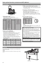
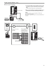
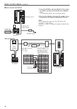
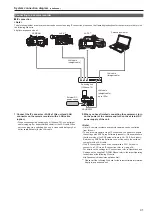
CCU control
- Control signals (camera, CCU control)
- Power supply (12 V DC)
*
1
*
1
Can be provided from CCU or AC adapter
PREVIEW control
: Contact output
Maximum cable length : 50 m (164 ft)
Operating temperature : 0 °C to 40 °C (32 °F to 104 °F)
Storage temperature
: −20 °C to 60 °C (−4 °F to 140 °F)
Humidity
: 90 % or less
Dimensions (W x H x D) : 92 mm x 308 mm x 55 mm (3-5/8 inches x
12-1/8 inches x 2-3/16 inches) (excluding
protrusions)
Mass
: approx. 1.3 kg (approx. 2.87lb)
Index
Numerics
12 DC V connector ..............................................................................
34
5600 K button ..........................................................................
12
,
20
,
27
A
Accessories ............................................................................................
7
Alarm display ...........................................................................
18
,
25
,
32
Auto Black Balance button ......................................................
11
,
20
,
27
Auto iris button .........................................................................
19
,
26
,
33
Auto setup ...........................................................................................
12
Auto Setup button ....................................................................
12
,
20
,
27
Auto White Balance button ......................................................
11
,
20
,
27
B
B flare/pedestal control ............................................................
14
,
21
,
28
B gain control ...........................................................................
14
,
21
,
28
C
Call button ...............................................................................
18
,
25
,
32
Camera number display ..........................................................
16
,
24
,
31
Camera number tens' place digit display .................................
16
,
24
,
31
Camera power button ..............................................................
11
,
20
,
27
Camera select button ..............................................................
16
,
24
,
31
CC filter ................................................................................................
15
CC filter display .......................................................................
15
,
23
,
30
CCU connector ....................................................................................
34
Character/Menu button ............................................................
18
,
25
,
32
Coarse control .........................................................................
19
,
26
,
33
Color Bar Signal Output button ................................................
11
,
20
,
27
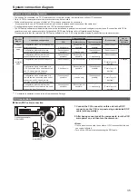
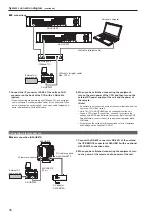
Connection ..........................................................................................
35
Control lock ..............................................................................
14
,
21
,
28
Control lock button ...................................................................
14
,
21
,
28
D
DATA SET button ....................................................................
15
,
22
,
29
Detail OFF button ....................................................................
12
,
20
,
27
Digital extender indicator .........................................................
19
,
26
,
33
Dip Switch ............................................................................................
34
DTL control ..............................................................................
14
,
21
,
28
E
EXECUTE button .....................................................................
16
,
24
,
31
EXIT button ..............................................................................
16
,
23
,
30
F
Fader full button .......................................................................
19
,
26
,
33
I
IP connection mode .............................................................................
10
IP connector ........................................................................................
34
Iris close button .......................................................................
19
,
26
,
33
IRIS display .............................................................................
15
,
22
,
29
Iris lever ...................................................................................
19
,
25
,
32
Iris/master pedestal lock button ...............................................
18
,
25
,
32
K
Knee OFF button .....................................................................
12
,
20
,
27
L
Lens extender indicator ...........................................................
19
,
26
,
33
M
Master pedestal control ...........................................................
19
,
25
,
32
Matrix button ............................................................................
12
,
20
,
27
Memory card access indicator .................................................
19
,
26
,
33
Memory card slot .....................................................................
19
,
26
,
33
M.GAIN display ........................................................................
16
,
23
,
30
M.GAIN/M.PED .......................................................................
16
,
23
,
30
M.GAIN/M.PED DISPLAY SELECT button .............................
16
,
23
,
30
M.PED display .........................................................................
16
,
23
,
30
N
ND filter ................................................................................................
15
ND filter/CC filter DISPLAY SELECT button ...........................
15
,
23
,
30
ND filter display .......................................................................
15
,
23
,
30
O
Operation modes .................................................................................
10
Optical alarm display ...............................................................
18
,
25
,
32
Outside dimension drawing ....................................................................
9
P
Preview button .........................................................................
19
,
25
,
32
Preview connector ...............................................................................
34
R
Rack mount brackets ..............................................................................
8
Rack mounting ........................................................................................
8
Red/green tally display ............................................................
18
,
25
,
32
R flare/pedestal control ............................................................
14
,
21
,
28
R gain control ..........................................................................
14
,
21
,
28
RS-422 connector ................................................................................
34
S
SAVE/LOAD button .................................................................
15
,
23
,
30
Scene file
Opening .......................................................................................
13
Storing .........................................................................................
13
SCENE/USER FILE select buttons .........................................
13
,
21
,
28
Scene/User File selector button ..............................................
13
,
21
,
28
Scene/user file store button .....................................................
13
,
21
,
28
Select dial ................................................................................
18
,
25
,
32
Sense control ...........................................................................
19
,
26
,
33
Serial connection mode .......................................................................
10
Setting display .........................................................................
15
,
22
,
29
SHUTTER ................................................................................
16
,
24
,
31
SHUTTER display ...................................................................
16
,
24
,
31
SHUTTER DISPLAY SELECT button .....................................
16
,
24
,
31
Shutter On/Off button ..............................................................
12
,
20
,
27
Skin Detail button ....................................................................
12
,
20
,
27
Specifications ......................................................................................
42
STEP/SYNC select button .......................................................
12
,
20
,
27
SYNCHRO display ..................................................................
16
,
24
,
31
U
User file
Opening .......................................................................................
13
Storing .........................................................................................
13
V
Viewfinder power button ..........................................................
11
,
20
,
27
Numerics
Summary of Contents for AK-HRP200G
Page 43: ...43 Memo ...


