


18
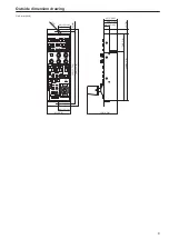
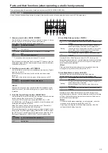
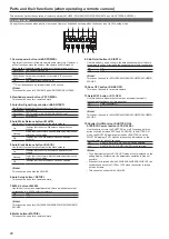
Parts and their functions (when operating a studio handy camera)
(continued)
19
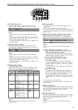
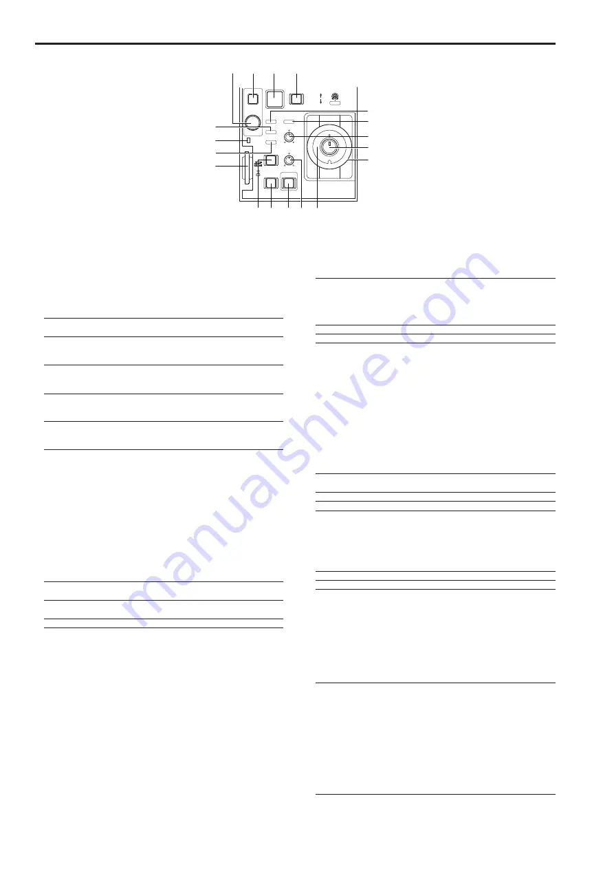
IRIS/M.PED LOCK
IRIS
M.PED
CHARA
MENU
SELECT
TALLY/CALL
ALM
OPT
SENSE
PUSH
PREVIEW
EXT
D.EXT
COARSE
AUTO
FULL
OPEN
CLOSE
CLOSE
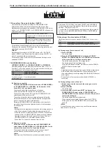
40
38
43
41
42
50
39
44
51
47
49
48
55
52
53
54
46
45
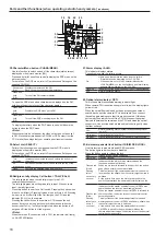
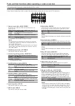
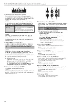
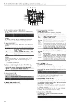
38.
Character/Menu button <CHARA/MENU>
Use this function to switch on and off the characters (status screen)
displayed on the picture monitor (PM).
Press and hold (for about 2 seconds) to display the ROP menu on the
picture monitor.
For details on the ROP menu, refer to Operations and Settings on the
supplied CD-ROM.
Short press
(On):
Displays characters on the PM.
Each short press changes the display data.
Press and
hold
(Off):
Turns off the PM character display.
To open the ROP menu when characters are displayed on the PM,
hold down the button to turn off the character display.
Press and
hold
(On):
Displays the ROP menu on the PM.
Press and
hold
(Off):
Turns off the ROP menu display on the PM.
To display characters when the ROP menu is open, hold down the
button to close the ROP menu.
<Note>
When characters do not appear, the video output has not been set
to PM. Since characters appear in SDI 3&4 or VBS output from the
CCU, make the settings that your operating environment requires.
39.
Select dial <SELECT>
Perform the following menu operations when the ROP menu is
displayed on the picture monitor (PM).
For details on the ROP menu, refer to Operations and Settings on the
supplied CD-ROM.
Turn
clockwise:
Increases the selected value and selects the bottom of
the menu
Turn
counterclockwise:
Decreases the selected value and selects the top of the
menu
Press:
Confirms the selected value and the menu
40.
Red/green tally display, Call button <TALLY/CALL>
The tally lights red when the red tally is input to the CCU
communication connector.
The tally lights green when the green tally is input. When both are
input, the tally lights red.
Press this button to use it as a Call switch. Pressing the button when
it is not on will light it. Pressing it when it is on will turn it off. Pressing
it when it is on or off will light the Call lamp on the CCU and the
indicator (TALLY) on the camera.
Pressing the call switch on the camera or CCU sounds the unit
buzzer. It stays on as long as the switch is depressed (when the
buzzer is set to On). The tally also lights red when the button is off,
but goes off if the button is lit red or green.
<Note>
When there is an IP connection with a CCU, the indicator (call lamp)
on AK-HC3800 flashes.
41.
Alarm display <ALM>
This indicator displays alarms.
Consult your supplier if a failure occurs.
On:
Lights when the camera fan stops due to a failure.
• Alarm data can be displayed on the CCU PM.
• When an alarm occurs, the Character/Menu button
<CHARA/MENU> on the unit lights and an alarm display
appears like an interrupt on the CCU PM.
Flashing:
Indicates that the power voltage of the unit has decreased
Off:
Normal operating status
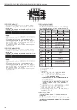
42.
Optical alarm display <OPT>
This is the optical transmission warning indicator light.
When camera/CCU reception strength level is low, the display lights
yellow or red.
When the optical fiber cable has not been properly connected or
seated, disconnect the camera/CCU optical cable. Then connect
the cable again making sure that it is properly seated. If this does
not remedy the problem, turn off the CCU, disconnect the optical
fiber cable between the camera and the CCU and clean the optical
connectors. Use a cotton swab moistened in alcohol to gently clean
the fiber surfaces.
Off:
Normal operating status (optical reception strength level
is 4 or 5)
On (green):
Optical reception level 2 or 3
On (red):
Optical reception level is 1, or the cable is disconnected
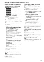
43.
Iris/master pedestal lock button <IRIS/M.PED LOCK>
Use this function to disable iris and M.PED operation.
The button lights red when they are disabled.
Press the button again to release the lock.
Off:
Iris and M.PED can be controlled
Lights red:
Disabled (locked)
Flashes red:
(Quick
flashing
rate of
once every
second)
Indicates that the Iris lever was operated when the
function was disabled (locked).
When the Iris lever is returned to lock position, the button
goes off and normal control is available.
This also flashes if the camera adjustment values and iris
lever position are offset when the control target camera is
switched.
At the point in time when the iris lever is moved to the
position that matches the camera adjustment values, the
button turns off and normal control becomes possible.
Flashes red:
(Slow
flashing
rate of once
every 2
seconds)
Indicates that the master pedestal control <M.PED> was
operated when the function was disabled (locked).
When the master pedestal control <M.PED> is returned to
the lock position, the button turns off and normal control
becomes possible.
This also flashes if the camera adjustment values and
master pedestal control <M.PED> position are offset when
the control target camera is switched.
At the point in time when the master pedestal control
<M.PED> is moved to the position that matches the
camera adjustment values, the button turns off and normal
control becomes possible.
Summary of Contents for AK-HRP200G
Page 43: ...43 Memo ...


