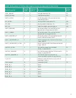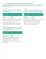
4.2 Communication network diagram
4.2.1 Functional description
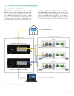
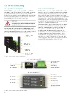
The flare.IQ Gen 2 has two independent unmanaged
8-port network switches installed on the top module –
one labeled flare control/DCS (Modbus TCP) and the
other labeled configure/monitor. As shown in figure 31
below, each DPU installed in the bottom module has
two independent ethernet ports – one dedicated to
a web console for configuration and monitoring via
the fiqWeb application described in Section 3.3 (LAN A),
and the other dedicated to Modbus TCP for exclusive use
by the plant DCS (LAN B). Any available Ethernet port on the
top switch may be used for the Modbus TCP connection
from the DCS, while any available port bottom switch may
be used for an IP connection to the fiqWeb web console.
To customer DCS (Modbus TCP)
To customer host PC web console (IP)
Bottom module in rack (3U)
DPU #1
DPU #2
DPU #3
Top module in rack (4U)
Ethernet #2 – flare control DCS (LAN B)
Ethernet #1 – configure/monitor (LAN A)
Figure 31: System I/O network connections
39
Summary of Contents for flare.IQ Generation 2
Page 1: ...flare IQ Generation 2 Operation and maintenance manual...
Page 2: ...2...
Page 3: ...flare IQ Generation 2 Operation and maintenance manual 910 350 rev A June 2020 3...
Page 4: ...no content intended for this page 4...
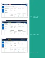
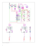
Page 38: ...Figure 30 System wiring diagram 38...
Page 48: ...48...

