• The assist pane displays the amount of supplemental
fuel, steam, or air being provided to the flare, as
measured by additional flowmeters, or determined
from control valve positions by the DCS.
• The non-HC gas composition pane displays the
concentration of non-hydrocarbon components in
the flare gas as determined by a gas chromatograph
(GC), mass spectrometer (MS), or calorimeter. If
available, the NHV and molecular weight of the
vent gas as determined by these instruments is
also displayed.
• The flare.IQ calculations pane displays results
calculated by the flare.IQ consisting of:
– NHV of vent gas (NHV
vg
) derived from the gas
composition and sound speed data
– Molecular weight (MW) of the vent gas derived from
the gas composition and sound speed data
– NHV in the combustion zone (NHV
CZ
) derived from
the gas composition and sound speed data
– Calculation of the flare gas velocity at the tip of
the flare stack (V
tip
)
3.3.6 Data status color
The monitor overview screen uses color to provide
additional information about the data displayed. The
top of the display presents the following color key:
• Data displayed in
green
is determined by the flare.IQ
to be valid, within programmed limits, and has been
recently updated.
• Data displayed in
red
is determined to be invalid.
This can be caused by the parameter never having been
sent by the DCS or is the result of a failed calculation
(for example, a divide by zero condition caused by
another parameter being invalid).
• Data displayed in
gray
is determined to be ‘stale’.
The result is valid, but it is marked as stale because
the parameter has not been recalculated or is the result
of a calculation using another parameter that has not
been updated by the DCS in a specified time period.
Most parameters are considered stale if they have
not been updated for 150 seconds (2.5 minutes).
Gas composition data is considered stale if it has
not been updated for the time specified as the
GC/MS update rate on the fuel settings page.
• Data displayed in
blue
is determined by the flare.IQ
to be below the low range limit determined for that
parameter. This is usually an indication of an error in
a parameter value supplied by the DCS.
• Data displayed in
orange
is determined by the
flare.IQ to be above the high range limit determined
for that parameter. This is usually an indication of
an error in a parameter value supplied by the DCS.
3.3.7 Modbus connection status
The status of the Modbus link between the DCS and the
flare.IQ is displayed in the heading bar. Note that this is
the network connection on LAN B. It is not an indication of
communication status between the browser displaying
the web console and the flare.IQ. Any issues with the
network connection on LAN A will appear as an http
error by the browser.
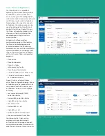
There are three Modbus connection states:
• Disconnected
– The DCS or other Modbus master
has not initiated a TCP session with the flare.IQ or has
disconnected/closed the TCP session. A disconnect is
assumed to have occurred if there is no traffic on the
designated port for 30 seconds (figure 22).
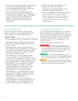
• Connected
– The DCS has initiated a TCP session
with the flare.IQ and is actively sending Modbus requests.
This is the normal state of system operation (figure 23).
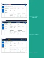
• Time Out
– The DCS has not disconnected/closed the
TCP session with the flare.IQ but has not sent a Modbus
request for more than 15 seconds (figure 23).
24
Summary of Contents for flare.IQ Generation 2
Page 1: ...flare IQ Generation 2 Operation and maintenance manual...
Page 2: ...2...
Page 3: ...flare IQ Generation 2 Operation and maintenance manual 910 350 rev A June 2020 3...
Page 4: ...no content intended for this page 4...
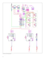
Page 38: ...Figure 30 System wiring diagram 38...
Page 48: ...48...


