1.4 Equipment installation
Users typically install the flare.IQ Gen 2 inside an
industrial control room that may include a plant
distributed control system (DCS), which controls multiple
flare system components such as flare, purge and assist
(steam/air) flow meters, valves, online BTU analyzers (e.g.
gas chromatographs, calorimeters) and temperature
and pressure regulators. It is intended for use in an office
environment with adequate temperature and RH controls.
This section contains information and instructions for
installing the flare.IQ Gen 2 in a plant (DCS) control room,
while considering all the above factors. Chapter 4 describes
in detail how to set up and connect the flare.IQ to the DCS.
If you have questions about the installation procedures,
contact our technical support department. See the rear
cover of this manual for contact information.
WARNING!
Installation shall be in an enclosed rack that
requires tool access.
You should discuss environmental and installation factors
with a Panametrics applications engineer or field service by
the time you receive the hardware. The equipment provided
should be suited to your application and installation site.
The flare.IQ Gen 2 is available only in a 19” rack-mount
version suitable for most indoor installations.
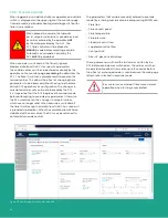
The power connections and power supplies are accessible
from the backside of the rack mount panel as shown in
figure 3. The end user brings in a non-detachable power
cord per the detailed specifications provided in Section 4.1.
WARNING!
Provisions have been made for landing
protective earth connection on appropriately
marked DIN rail mounted grounding modules
as shown in figure 4. The ground module
is electrically connected to the DIN rail,
which in turn is connected to the chassis
via a PEM fastener. The power cord’s ground
wire (25 – 14 AWG) terminates singly in the
protective earth grounding module (figure 4)
which includes captive screws.
Redundant 3.8A
24 VDC universal
input power supplies
Mini circuit breaker
distribution, and
input source
grounding
Diode redundancy
module for DPU
power
Figure 3: Rear view showing input power connections and power supplies
Protective earth
connections
Figure 4: Rear view close-up of top module showing protective
earth grounding
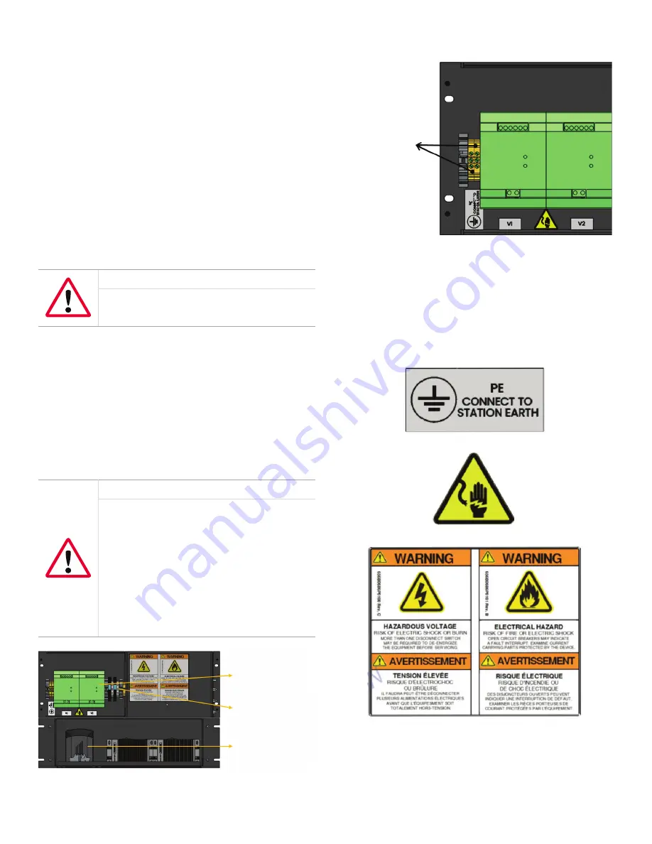
Figure 5 provides a detailed explanation of all the
warning symbols and labels applied to the flare.IQ
Gen 2 hardware. In addition to following all installation
and operation instructions in this user manual, be sure
to follow all applicable safety codes and regulations for
installing electrical equipment in your area.
Protective earth ground label
Electrical shock warning label
System hazardous voltage warning label (English/French)
Figure 5: Description of warning symbol labels applied to the top module
11
Summary of Contents for flare.IQ Generation 2
Page 1: ...flare IQ Generation 2 Operation and maintenance manual...
Page 2: ...2...
Page 3: ...flare IQ Generation 2 Operation and maintenance manual 910 350 rev A June 2020 3...
Page 4: ...no content intended for this page 4...
Page 38: ...Figure 30 System wiring diagram 38...
Page 48: ...48...

