2.2 Power supply
2.2.1 Functional description
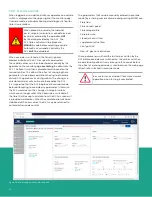
The MINI POWER is a 24 VDC, 3.8 A supply, with a wide input
power range (100 – 240 VAC). Two internal DC/DC converters
convert supply power into an adjustable and regulated 24 V
output voltage. Two MINI POWERs are connected in parallel
(load sharing) to create a high reliability (redundant)
supply. Reliable startup of heavy loads is ensured by a
power reserve of up to 100%. MINI POWER also operates in
applications where the static voltage dips or in transient
power supply failures. Powerful capacitors ensure mains
buffering of more than 20 ms at full load.
The mechanical structure and the housing of this power
supply are largely determined by its compliance with safety
regulations, and thus the possible installation location of
the power supply unit. According to EN 60529, particular
attention must be paid to shock protection, foreign
body protection and water protection. These degrees of
protection are listed in the IP (ingress protection) code.
Generally, IP 20 protection is adequate for dry rooms and
control cabinets. This degree of protection ensures reliable
protection from touching live components and prevents
penetration of foreign particles with a diameter of more
than 12.5 mm (0.5 in.). Protection against water is not
provided. In this application, the power supply is installed
in a rack-mounted control cabinet, which itself ensures the
desired degree of protection.
For this power supply with class of protection I, protection
against electric shock is not only based on the insulation
rating. In addition, parts are connected to the protective
conductor of the permanent installation in such a way that
no voltage can remain even if the basic insulation fails.
Hence, the system is always provided with a protective earth
(PE) ground connection. These units are usually grounded
using the PE connection on the AC input terminal. The power
supply unit is electrically connected to the mounting DIN rail
via the mounting rail adapter. PE connection via the terminal
point is not required if the mounting rail is grounded.
2.3 Network switch
2.3.1 Functional description
GE’s industrial ethernet 10/100 switches are designed
specifically to meet the needs of real-time industrial
control solutions. The ethernet switch model used in this
application is an 8-port 10/100 base T copper cables only,
IS420ESWAH2A. To meet the requirements for speed and
functionality, the following features are provided:
• 802.3, 802.3u, and 802.3x compatibility
• 10/100 base T copper with auto negotiation
• Full/half duplex auto-negotiation
• Two 100 base FX uplink ports
• HP-MDIX auto sensing
• LEDs for link presence, activity and duplex, and speed
per port (each LED has two colors)
• LED for power
• Minimum 256 KB buffer with 4K media access control
(MAC) addresses.
Flow control (pause)
The switch supports flow control between switches. It uses
IEEE defined pause packets to receive and honor pause
packets. The switch only sends the pause packets if it needs
flow control on a port.
Connectors
The RJ-45 connectors support multiple insertions and
removals with an estimated service life expectancy of 200
insertion/removal cycles.
Mounting
The two ethernet switches labeled Ethernet #1 (configure/
monitor) and Ethernet #2 (flare control/to DCS) are mounted
in the 4U top power distribution and networking module.
Power
Supports two redundant diode-OR’d power supply inputs of
18 to 36 V DC, < 0.5A (total).
Environment
Convection cooled when mounted vertically or horizontally.
Coating is corrosion resistant with provisions made for
grounding per IEC 60721-3-3 Class 3C2.
Diagnostics
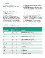
The two status LED’s indicate diagnostic information as show
in table 1 below.
Table 1: Network switch diagnostic indicators
LED one
Flashes green for activity at full duplex
Flashes yellow for activity at half duplex
LED two
Green = link and 100 Mb
Yellow = link and 10 Mb
No LED lit = no link
14
Summary of Contents for flare.IQ Generation 2
Page 1: ...flare IQ Generation 2 Operation and maintenance manual...
Page 2: ...2...
Page 3: ...flare IQ Generation 2 Operation and maintenance manual 910 350 rev A June 2020 3...
Page 4: ...no content intended for this page 4...
Page 38: ...Figure 30 System wiring diagram 38...
Page 48: ...48...

