3.3.9 Flare meter validation
The flare.IQ Gen 2 system is designed to operate at any
GF868/XGF868i installation that employs a Modbus
RTU or Modbus TCP connection between the Panametrics
flare flow meter and the DCS. The DCS acts as the Modbus
master reading diagnostic data from the GF868/XGF868i
and writing them to flare.IQ Gen 2. The Gen 2 system is
designed to operate on an independent Modbus TCP
network without interrupting an
existing installation of flare.IQ Gen 1
used for flare control. The basic logic
of the digital meter verification feature
is described in Section 3.2.2.
When enabled by a valid license,
digital verification will be performed
automatically on the 1st of every
calendar month at 01:15 AM UTC.
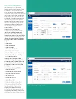
Figure 26 shows the validation page
of the web console that enables
an on-demand digital verification
on a specific flare flow meter. Your
Panametrics field service engineer will
ensure that the firmware and digital
communication hardware of the flare
flow meter (GF/XGF) is at the correct
version and the units of measure
(English/metric) are set consistently
between flare.IQ Gen 2 and the
flare flow meter. They will configure
the digital verification feature at
commissioning by uploading a
site-specific meter configuration file
via the service page.
As shown in figure 10, running digital
verification requires a minimum
amount of meter diagnostic data
collected over an 8-hour time window.
This ensures verification occurs only
when stability criteria for all flow meter
diagnostics are adequately satisfied.
The “VALIDATE NOW” button on the
validation page in figure 26 will be
enabled only when this condition is
met. The maximum data interval for
sending all GF/XGF Modbus data from
the DCS to flare.IQ Gen 2 is 3 minutes.
Occasional communication dropouts
that lead to data intervals greater
than 3 minutes are acceptable. In
case of loss of power to flare.IQ Gen 2,
all validation data accumulated
in the FIFO buffer is lost. Hence, an
on-demand verification request will
need to wait for 8 hours after power
has been restored for the buffer to
be refilled.
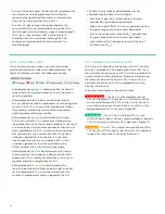
Figure 27 shows the results of a passing
digital verification for a 2-channel
flow meter. The date and time the last validation was
completed (regardless of the result) are shown in the top
right corner. The results of sound speed validation vis-à-vis
an online gas analyzer are shown on top while the results of
the diagnostics validation based on meter configuration-
specific pass/fail criteria are listed in the table is shown in
the bottom.
Figure 26: Validation page showing system is ready for on-demand digital verification
Figure 27: Validation page showing typical result for passing digital verification
27
Summary of Contents for flare.IQ Generation 2
Page 1: ...flare IQ Generation 2 Operation and maintenance manual...
Page 2: ...2...
Page 3: ...flare IQ Generation 2 Operation and maintenance manual 910 350 rev A June 2020 3...
Page 4: ...no content intended for this page 4...
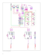
Page 38: ...Figure 30 System wiring diagram 38...
Page 48: ...48...

