6.2 DASH SECTION INSTALLATION
Note: If you have not already done so, read sections 4.0 and 5.0 of these
instructions and think through the installation of the harness before securing or
cutting any wires.
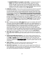
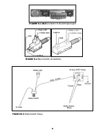
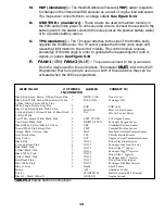
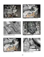
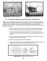
The wires in this group consist of the diagnostic link connector (DLC) (SEE FIGURE 6.1), the
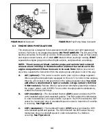
check engine light (pre-mounted into a mounting bracket), fuel pump relay, emissions devises
(optional) and 6 other wires.
CAUTION: DO NOT MAKE ANY CONNECTIONS WHILE THE COMPUTER IS PLUGGED
INTO THE HARNESS.
Note: Wire color (Example: Blk/Wht) is one wire with a stripe. The second color
(the stripe) may not be bold. Observe all two-color wires closely.
A. AC REQUEST –
This circuit is used to inform the PCM that the AC compressor has been turned on. This
wire is to be spliced into the circuit from the AC switch to the AC compressor.
This is not a power supply for the compressor
B. The secondary Air Injection (AIR) system helps reduce hydrocarbon (HC), carbon
monoxide (CO), and oxides of nitrogen (NOx) exhaust emissions.
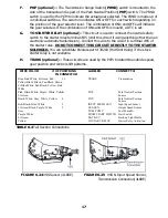
1. AIR PUMP (not equipped on all models) - The AIR pump assembly is mounted
in the right rear corner of the engine compartment and supplies the air to the AIR
system. The electric air pump sends air to the check valves near the exhaust
manifolds. The AIR pump is controlled by the Powertrain Control Module (PCM)
through the AIR pump solenoid relay. Battery voltage to the AIR pump is controlled
by the AIR pump solenoid relay. A vacuum operated shut off valve prevents air flow
during OFF periods. When the PCM provides a ground circuit for the secondary AIR
pump solenoid relay, battery voltage applies power to the AIR pump and the
solenoid. Intake manifold vacuum is then applied through the solenoid to the
vacuum operated shut off valve. The vacuum operated shut off valve then opens up
and allows air to be delivered to the check valves. See Figure 6.7
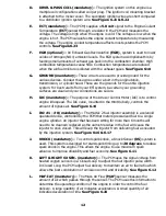
2. AIR RELAY (not equipped on all models) - The PCM controls the operation of
the AIR system through the AIR pump solenoid relay. When the PCM provides a
ground circuit for the secondary AIR pump solenoid relay, battery voltage is allowed
to power up the AIR pump and the solenoid. See Figure 6.4
3. AIR SOL (not equipped on all models) - The AIR solenoid is activated by the
AIR pump solenoid relay. The AIR solenoid allows intake manifold vacuum to the
shut off valve. The shut off valve then opens allowing air flow. See Figure 6.8
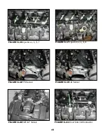
4. CAN VENT (not equipped on all models) - The Evaporative Emissions (EVAP)
control system used on all vehicles is the charcoal canister storage method. This
method transfers fuel vapor from the fuel tank to an activated carbon, charcoal,
storage device, canister, to hold the vapors when the vehicle is not operating. When
the engine is operating, the fuel vapor is purged from the carbon element by intake
air flow and consumed in the normal combustion process. See Figure 6.6
7


