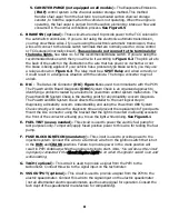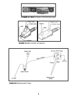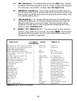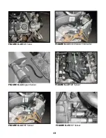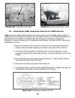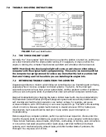
FIGURE 6.8 Air Solenoid
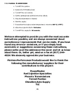
FIGURE 6.9 Fuel Pump Relay Connector
6.3 ENGINE GROUP INSTALLATIONS
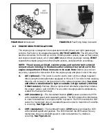
The engine group is designed to be separated into left (driver) and right (passenger)
sections. Each side is tie-wrapped separately, BUT NOT LABELED. The left side of the
has the connectors for the idle air control, throttle position sensor, mass air flow sensor,
and engine coolant sensor, all of which ARE labeled. When you begin routing, FIRST
separate the engine group into left and right sections, and place them accordingly.
NOTE: The air pump, air bleed, canister purge, and canister vent solenoid
connectors are rolled up in the dash section and must be routed out to the
engine compartment if these items are to be used. Note: Before you connect
any wires, separate the tail section from the engine group and place it out of the way.
A.
ALT (optional) - This circuit is used to excite (turn on) the voltage regulator.
When using the stock alternator equipped on the 4.8, 5.3 or 6.0L Vortec engines,
this wire will connect to the L terminal in the voltage regulator plug. You must
add either a small indicator light or suitable voltage reducer (82 Ohm/
5 Watt resistor). Painless offers a replacement alternator pigtail that includes
the proper resistor, part #30705. For any other charging system combinations,
contact the Painless tech dept.
B.
CKP (mandatory) - The Crankshaft Position (CKP) sensor provides the PCM
with crankshaft speed and crankshaft position. The PCM utilizes this information
in order to determine if an engine misfire is present. The PCM monitors the CKP
sensor for momentary drop in crankshaft speed in order to determine if a misfire
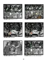
is occurring. See Figure 6.15
C.
CMP (mandatory) - The Camshaft Position (CMP) sensor provides the PCM
with camshaft speed and position. The PCM monitors the CMP sensor for any
momentary drops in camshaft speed in order to determine if a misfire is
occurring. See Figure 6.14
11


