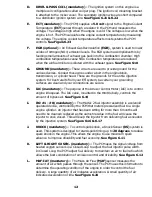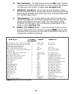
5. CANISTER PURGE (not equipped on all models) - The Evaporative Emissions
(EVAP) control system is the charcoal canister storage method. This method
transfers fuel vapor from the fuel tank to an activated carbon charcoal storage
canister, to hold the vapors when the vehicle is not operating. When the engine is
operating, the fuel vapor is purged from the carbon element by intake air flow and
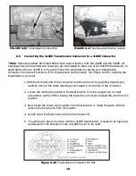
consumed in the normal combustion process. See Figure 6.5
C. BRAKE SW (optional) - These circuits are used to provide power to the TCC solenoid in
the automatic transmission. If you are not using the electronic automatic transmission,
you may stow these wires. If you are using the electronic automatic transmission, these
wires will connect to the brake switch terminals that are normally used for cruise control
or TCC solenoid (normally closed). These wires do not connect to the terminals for
the brake lights.
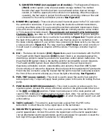
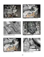
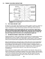
D. DLC - The Data Link Connector (DLC) Figure 6.1 is used to communicate with the PCM.
The Powertrain On Board Diagnostic (OBD) System Check is an organized approach to
identifying a problem created by an electronic powertrain control system malfunction. The
Powertrain OBD System Check is the starting point for any drivability concern diagnosis.
The Powertrain OBD System Check directs the installer to the next logical step in
diagnosing a drivability concern. Understanding and using the Powertrain OBD System
Check correctly will reduce the diagnostic time and prevent the replacement of good parts.
Mount the DLC connector using the bracket that the light is mounted in allowing access to
the front of the connector allowing you to see the light while driving. See Figure 6.1
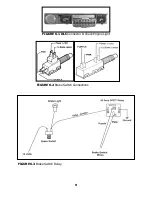
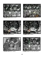
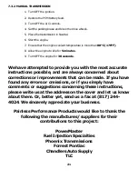
See table 4.1 for the recommended brake switch. If you are using the
recommended brake switch then you will wire it according to Figure 6.2. The pink wire to
the back of the switch in the illustration is the wire that has power on it whether or not
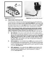
the brake is being applied. If your vehicle has a pressure type brake switch, you may use
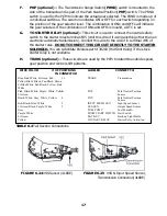
a relay as shown in Figure 6.3. The relay must be a SPDT Relay and wired correctly or
it could result in a dangerous situation with the vehicle. The torque converter may not
unlock.
E. FUEL TEST (use as needed) - This circuit is used to power the electric fuel pump for
test purposes only. Temporarily apply fused positive power to this wire for testing the fuel
pump.
F. FUSE BLOCK IGNITION (mandatory) - This circuit is used to provide power to the
injection system. Connect this wire to a terminal/ wire from the ignition switch that is hot
in the
RUN and CRANK
positions. Failure to provide power in the crank position will
result in PCM shutdown while the engine is trying to start.
Note: You will know this circuit
is properly connected if the Check Engine Light is on when the ignition switch is on and
while starting.
G. TACH (optional) - This circuit is used to provide a signal from the PCM to the
tachometer. Connect this wire to the signal input on the tachometer.
H. VSS OUTPUT (optional) - This circuit is used to provide a signal from the PCM to the
electric speedometer. Connect this wire to the signal input on the electric speedometer
(not all aftermarket electric speedometers use the same signal for operation. Consult the
tech dept of the speedometer manufacture for compatibility).
8


