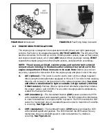
5.1.1 Connect a ground strap or cable (minimum of a 4 Ga. wire) from the negative
battery terminal to the chassis (frame).
5.1.2 Connect a ground strap (minimum of a 4 Ga. wire) from the engine to the
chassis (frame). Do not rely upon the motor mounts to make this connection.
5.1.3 Connect a ground strap from the engine to the body.
5.2 ROUGH INSTALLATION
CAUTION: DISCONNECT THE POWER FROM YOUR VEHICLE BY REMOVING THE
NEGATIVE BATTERY CABLE FROM THE BATTERY.
Note: Make no wire connections or permanent mounting of any kind at this time.
5.2.1 Position the computer and sensors in their intend locations.
5.2.2 Drill a 1-5/8" hole for the firewall grommet near the computer for the engine
group and tail section to pass through.
5.2.3 Route the engine group and tail section through the hole. Push the grommet
(already installed on the harness) into the hole until it is seated.
5.2.4 Route the dash group over to the driver's side of the car.
5.2.5 Route the fuse block and relays to the place they will be mounted.
5.3 HARNESS ATTACHMENT
Note: Harness routing and shaping will be a time-consuming task. Taking your time
will enhance the beauty of your vehicle. Please take your time and be patient.
5.3.1 Permanently mount your computer. You should mount the fuse block and relays
at this time.
5.3.2 Mold harness groups to the contour of the dash, engine, frame, etc. Remember
to route harness away from sharp edges, exhaust pipes, hinges, and moving parts.
5.3.3 Attach harness groups to your automobile with clips or ties starting at the
computer and working your way outward.
Note: Do not tighten tie wraps or mounting devices at this time. Make all harness
attachments LOOSELY.
5.3.4 When used every 1-1/2" or so on the visible areas of the harness, colored plastic
wire ties make a very attractive assembly. Otherwise, a tie installed in other areas every
6" or so will hold the wires in place securely. REMEMBER TO TAKE YOUR TIME.
5


