background image

46

MAKING HDTV-DISPLAY SETTINGS (cont.)
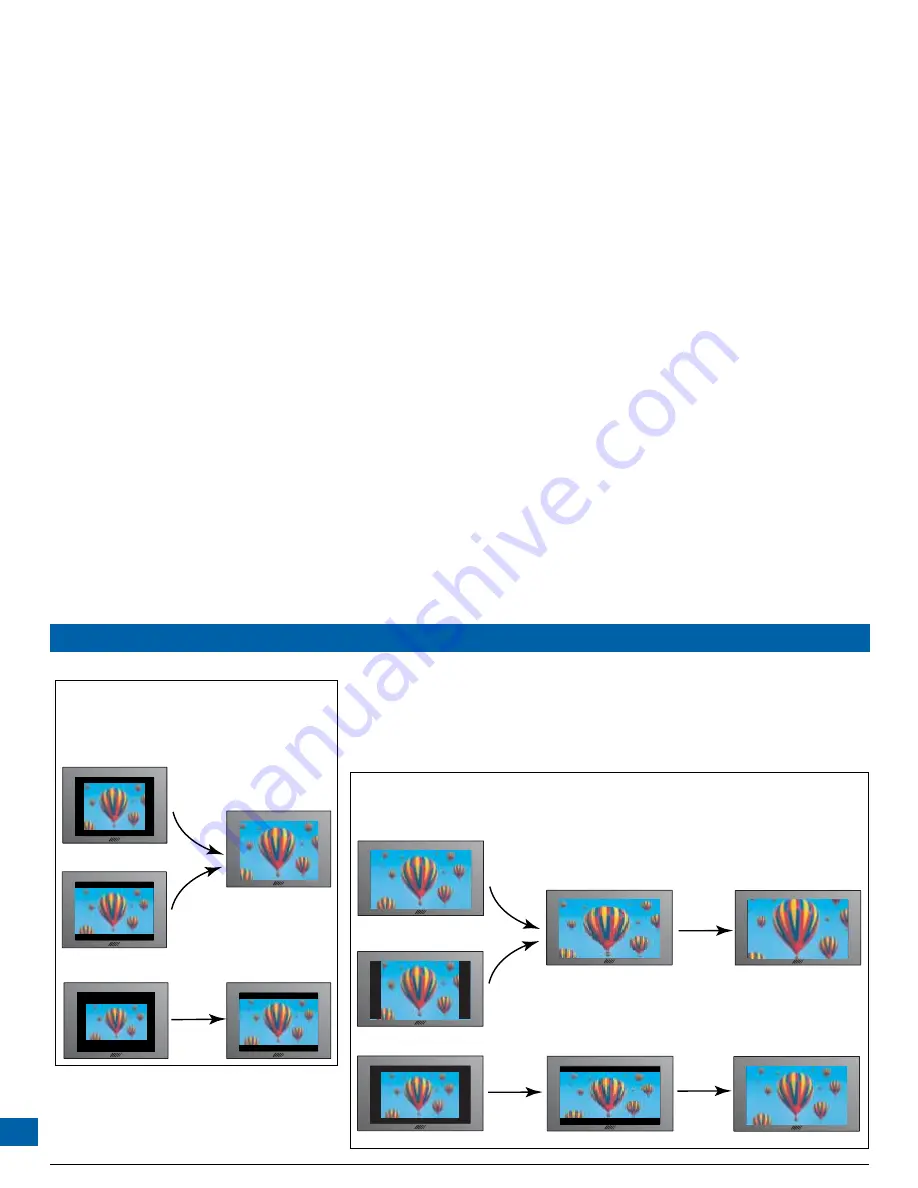
Press Zoom button

Press Zoom 

button

Reduced picture sizes you may see, 
depending on the different ways 
the picture can be transmitted

Pressing the Zoom button 
causes a zooming of the 
picture so that it better fits 
the screen. The symbol 480p 
appears briefly on the screen 
when you do this zooming.

EXAMPLE 1:  you have a 4:3 HDTV, connected by HDMI or COMPONENT VIDEO 
jacks, and the menu settings are 1080i (or 720p) and 4:3

Press Zoom button

Press Zoom 

button

Picture sizes you may see, 
depending on the different ways 
the picture can be transmitted

Pressing the Zoom button once 
causes a stretching of the picture so 
that it fits the screen from 
side-to-side. However, you may 
prefer to press Zoom again to zoom.

EXAMPLE 2:  you have a 16:9 HDTV, connected by HDMI or COMPONENT VIDEO jacks, and the menu settings are 1080i (or 720p) and 16:9

Press Zoom 

again

STRETCH: picture-content is 
maintained for those pictures 
that had dark bars, but images 
are stretched sideways

ZOOM: images are properly shaped, 
but content is sometimes lost at 
the top and bottom of the screen 
or at the sides.

Press Zoom 

again

Summary of Contents for TDC775D

Page 1: ...or registered trademarks of Pace Micro Technology plc HDMI the HDMI logo and High Definition Multimedia Interface are trademarks or registered trademarks of HDMI Licensing LLC Other trademarks listed...

Page 2: ...optional home theater 31 Set up I VCR DVD Home Theater and Component video HDTV 34 CONNECTING TO THE AC POWER SUPPLY 36 Connecting the TV to the AC power supply 37 Connecting the power cord to the se...

Page 3: ...NTION Other warnings TO REDUCE THE RISK OF ELECTRIC SHOCK DO NOT REMOVE THE COVER OF THE SET TOP THERE ARE NO USER SERVICEABLE PARTS INSIDE IT TO REDUCE THE RISK OF FIRE OR ELECTRIC SHOCK DO NOT EXPOS...

Page 4: ...des and a third grounding prong The wide blade or the third prong are provided for your safety If the provided plug does not fit into your outlet consult an electrician for replacement of the obsolete...

Page 5: ...ing accessory recommended by the manufacturer See also item 12 in the Important Safety Instructions Ventilation Slots and openings in the casing of the set top are provided for ventilation to ensure r...

Page 6: ...ines You must not locate an outside antenna system in the vicinity of overhead power lines or other electric light or power circuits or where it can fall into such power lines or circuits When install...

Page 7: ...r panel are on page 10 Connecting Do not connect the set top or any other equipment such as a TV or VCR to the power supply until you have properly connected all the other cables The set top operates...

Page 8: ...every hour You should avoid using the Web if you are tired or have lost some sleep Regulatory information CAUTION Do not attempt to modify the set top without written authorization from the manufactu...

Page 9: ...do not yet connect the power cords see page 15 through 35 Connect the power cords and turn on the equipment see page 36 through 38 Check that you can see a picture on theTV and do any necessary tunin...

Page 10: ...o display HDTV settings see page 43 L R U and D To move left right up down in an on screen menu guide channel U U U U and D D D D To change channel up or down menu To display on screen menus bypass To...

Page 11: ...RECEIVE Infra red input from a remote eye SECONDARY AUDIO OUT Audio baseband outputs stereo L and R TO TV RF output to the TV or VCR ETHERNET For future use UNIVERSAL SERIAL BUS USB For future use COM...

Page 12: ...video baseband output on a DVD player or similar USB UNIVERSAL SERIAL BUS Connect to compatible optional equipment that supports a USB 1 1 interface for example a printer digital camera keyboard or m...

Page 13: ...be 75 coaxial not regular audio cable Cable type Connector type Cable numbers Drawn as 75 coaxial male F type HDMI HDMI 19 pin type A 1 HDMI to DVI HDMI 19 pin type A 2 Component video 75 coax male RC...

Page 14: ...or infrared sensor 2 Select a location on theVCR to attach the IR emitter This must be within 3 inches of the remote control sensor Make sure the area is clean and dry 3 Remove the covering from the...

Page 15: ...tween the remote control and the remote eye 2 Make sure that you can conveniently route the cable The cable on the remote eye is approximately 10 feet long so make sure that the location you have chos...

Page 16: ...pressing the power button on the front panel When the set top is in standby the light beside the power button is red If you activate baseband loopthrough the following occur COMPONENTVIDEO IN loops t...

Page 17: ...O IN HOME THEATER RECEIVER OPTICAL AUDIO IN COAXIAL AUDIO IN DIGITAL AUDIO IN POWER 8 1 RF CABLE ANTENNA RF IN LEFT AUDIO IN RIGHT AUDIO IN VIDEO IN POWER HDTV PB CB IN PR CR IN Y IN COMPONENT VIDEO I...

Page 18: ...arries both high resolution digital video and digital audio To enhance the sound you can connect a home theater receiver There is a choice of two S PDIF outputs i electrical labeled DIGITAL AUDIO OUT...

Page 19: ...O IN HOME THEATER RECEIVER OPTICAL AUDIO IN COAXIAL AUDIO IN DIGITAL AUDIO IN POWER 8 2 RF CABLE ANTENNA RF IN LEFT AUDIO IN RIGHT AUDIO IN VIDEO IN POWER HDTV PB CB IN PR CR IN Y IN COMPONENT VIDEO I...

Page 20: ...o DVI cable 2 to connect it to the set top s HDMI Both DVI and HDMI carry high resolution digital video Use baseband audio cables cable 3 from the set top s PRIMARY AUDIO OUT jacks to the HDTV s baseb...

Page 21: ...UDIO OUT VIDEO OUT VCR POWER S VIDEO OUT S VIDEO IN 8 1 7 5 4 6 CABLE INPUT LEFT AUDIO IN RIGHT AUDIO IN VIDEO IN POWER HDTV S VIDEO IN HDMI ANTENNA RF IN TV RF OUT PB CB IN PR CR IN Y IN COMPONENT VI...

Page 22: ...75 ohm coaxial cables Use baseband audio jack cables cable 6 from the set top s PRIMARY AUDIO OUT jacks and cable 7 between theVCR and the HDMITV The path for recording on theVCR is cables 6 baseband...

Page 23: ...o Video Audio Video RF Cable TV Cable Wiring Diagram C TDC775D set top VHS Recorder HDTV Cable TV RF A V RF Cable TV HDMI or DVI Audio TDC775D set top Home Theater HDTV Cable TV RF Cable Wiring Diagra...

Page 24: ...INPUT 8 7 LEFT AUDIO IN RIGHT AUDIO IN VIDEO IN POWER HDTV PB CB IN PR CR IN Y IN COMPONENT VIDEO IN S VIDEO IN LEFT AUDIO IN RIGHT AUDIO IN HDMI ANTENNA RF IN TV RF OUT ANTENNA RF IN RF CABLE RF CABL...

Page 25: ...theater receiver the set top s audio connection to theTV via HDMI is not needed so you may wish to mute turn off the audio on theTV Instead of theVCR s baseband audio output going to theTV it connect...

Page 26: ...UT DVD PB CB PR CR Y COMPONENT VIDEO OUT DIGITAL AUDIO OUT OPTICAL COAXIAL POWER 8 1 10 9 RF CABLE ANTENNA RF IN LEFT AUDIO IN RIGHT AUDIO IN VIDEO IN POWER HDTV PB CB IN PR CR IN Y IN COMPONENT VIDEO...

Page 27: ...ayer has component video output jacks and you make the connection using three cables 9 If it does not have component video outputs then you can connect it to the HDTV using any spare baseband video or...

Page 28: ...AUDIO OUT RIGHT AUDIO OUT VIDEO OUT CABLE INPUT VCR DVD LEFT AUDIO IN VCR IN RIGHT AUDIO IN VIDEO IN PB CB PR CR Y COMPONENT VIDEO OUT HOME THEATER RECEIVER OPTICAL AUDIO IN COAXIAL AUDIO IN DIGITAL...

Page 29: ...necessary to do this and it requires more cables When you add a home theater receiver as shown the set top s audio connection to theTV via HDMI is not needed so you may wish to mute turn off the audi...

Page 30: ...OME THEATER RECEIVER OPTICAL AUDIO IN COAXIAL AUDIO IN DIGITAL AUDIO IN POWER 8 3 12 ANTENNA RF IN LEFT AUDIO IN RIGHT AUDIO IN VIDEO IN POWER HDTV PB CB IN PR CR IN Y IN COMPONENT VIDEO IN S VIDEO IN...

Page 31: ...p In addition connect baseband audio cables 3 between the PRIMARY AUDIO OUT jacks on the set top and the baseband audio in jacks on the HDTV To enhance the sound you can connect a home theater receive...

Page 32: ...AUDIO IN POWER 8 3 9 12 ANTENNA RF IN LEFT AUDIO IN RIGHT AUDIO IN VIDEO IN POWER HDTV PB CB IN PR CR IN Y IN COMPONENT VIDEO IN S VIDEO IN LEFT AUDIO IN RIGHT AUDIO IN DVD PB CB PR CR Y COMPONENT VI...

Page 33: ...audio input jacks on the HDTV If the HDTV s audio inputs are limited you can use the set top s baseband audio loopthrough feature to loop the audio through the set top cables 10 and 3 as shown The se...

Page 34: ...33 CONNECTING THE EQUIPMENT cont RF Cable TV Y Pb Pr Video TDC775D set top Home Theater HDTV Cable TV RF Cable Wiring Diagram H DVD Player Digital Audio Y Pb Pr Video Digital Audio...

Page 35: ...IN VIDEO IN POWER HDTV PB CB IN PR CR IN Y IN COMPONENT VIDEO IN S VIDEO IN LEFT AUDIO IN RIGHT AUDIO IN DVD PB CB PR CR Y COMPONENT VIDEO OUT DIGITAL AUDIO OUT OPTICAL COAXIAL POWER 11 LEFT AUDIO OUT...

Page 36: ...audio from the set top to theVCR could be looped through the home theater receiver it is not necessary to do this and it requires more cables Although the component video output from the DVD player g...

Page 37: ...HT AUDIO IN VIDEO IN LEFT AUDIO OUT RIGHT AUDIO OUT VIDEO OUT CABLE INPUT VCR DVD LEFT AUDIO IN VCR IN RIGHT AUDIO IN VIDEO IN PB CB PR CR Y COMPONENT VIDEO OUT HOME THEATER RECEIVER OPTICAL AUDIO IN...

Page 38: ...equipment into AC wall outlets If these outlets have switches switch them ON WARNINGS Do not connect the set top or any other equipment such as aTV orVCR to the AC power supply until you have properly...

Page 39: ...that is suitable for the installation location and should have told you which channel this is You must tune the TV and the VCR to this output channel so that programs can be watched and recorded thro...

Page 40: ...ep 2 Tune theVCR by setting theVCR s RF output channel to the same RF channel number as the set top andTV either 3 or 4 as stated by the cable operator Everything should now be tuned correctly NOTE Re...

Page 41: ...use the TV s remote control to tune to any of the regular analog channels and watch that channel on the TV At the same time you can record a different channel digital or analog on the VCR For this to...

Page 42: ...el that the set top is tuned to If however the TV is an HDTV or has additional inputs such as baseband inputs and has been connected up as shown on pages 15 to 35 you can watch the channel that the se...

Page 43: ...been watching Record high definition digital video Record one program while watching another Record two programs while watching a previously recorded program Schedule the set top to record a program...

Page 44: ...L R U D and select buttons on the front panel to change the settings Check and change the settings by looking at the set top s front panel You can also look at the on screen menus although please note...

Page 45: ...ront panel press the R button to highlight the setting for that item or open the sub menu if there is one On sub menus press the front panel U or D button until you highlight the item you want 3 Press...

Page 46: ...4 3 pictures are transmitted in high definition format In these cases dark bars are transmitted as part of the picture as shown In addition in some circumstances the set top and or the TV itself may a...

Page 47: ...oom button Press Zoom button Picture sizes you may see depending on the different ways the picture can be transmitted Pressing the Zoom button once causes a stretching of the picture so that it fits t...

Page 48: ...ake the settings See also the instructions below 1 To change theTV Aspect Ratio press the R button The currentTV Aspect Ratio 4 3 or 16 9 displays on the front panel Depending on the set up you may al...

Page 49: ...acks is always the standard definition 480i If equipment is connected via an HDMI cable it may also pass information back to the set top which may affect what settings are available 480i transmission...

Page 50: ...splays If this is the correct setting press the L button The front panel will display 1080 again If you want to change the setting press U or D On the on screen menu the highlight moves between the av...

Page 51: ...add black bars to the 4 3 picture so that it is transmitted to the TV at a 16 9 aspect ratio See the example below Changing the Auto Pillarbox setting If you have not done so already put the set top i...

Page 52: ...in a 4 3 transmission Sometimes 4 3 transmissions may contain a 16 9 picture with black borders at the top and bottom On a 16 9 TV this may display with black borders all the way around the picture T...

Page 53: ...t the set top into HDTV settings mode as described on page 43 The front panel displays ASPt 1 To change the Closed Captions setting press the D button until the front panel displays CC as shown right...

Page 54: ...andard caption service is CC1 Hi Def CC refers to one of 6 possible closed caption services Digital 1 to Digital 6 that you can select for high definition channels These are used for different languag...

Page 55: ...e D button until the front panel displays brit as shown right 2 Press the R button The Front Panel Setting menu shown right displays 3 Press the U or D buttons to highlight Dim Level or Bright Level a...

Page 56: ...you have made will be lost and the settings will revert to those which were programmed in the factory The factory settings are HDTV menu item Options Factory default setting TV Aspect Ratio 16 9 TV D...

Page 57: ...elect button 4 The factory settings are restored If you want to continue changing the settings press L then see the sections from page 43 onwards If you have finished changing the settings press the p...

Page 58: ...wer from this AC outlet will switch off when the set top is put in standby If set to Unswitched the AC outlet is always on so any TV that is receiving its power from this AC outlet will continue to re...

Page 59: ...rol operate the set top Please see the next page The set top may not be turned on Check if the light beside the power button on the front panel is blue If it is red press the power button on the front...

Page 60: ...w the system is connected up If the video path between the set top and the TV loops through other equipment such as aVCR you may need to turn off this equipment for the loopthrough to work Check the H...

Page 61: ...e and hear a DVD that you are trying to play For the signal to loop through the set top from a DVD or similar equipment to reach the TV you must activate baseband loopthrough by turning off the set to...

Page 62: ...let on the set top s rear panel it will be affected by a menu item called AC Outlet If this is set to Switched then when you turn on the set top to record on theVCR the attached HDTV will also turn on...

Page 63: ......

Reviews: