3-4
u
Operation
F
RONT
P
ANEL
Front Panel and Media Locks
To avoid accidental interruption of module operation by entering the Menu Mode while the host
is accessing the module, you can lock the Control Panel electronically using the Security Menu.
Once you have locked the Control Panel, you must use an unlock code to enter the Menu Mode.
This prevents access to the Unlock Door item on the Main Menu. (Refer to
later in this chapter.)
You can also lock and unlock the media using the host software's SCSI Allow/Prevent Medium
Removal command. If there is a host failure, you can restore media access by cycling
PowerLoader power.
Display Messages
The display on the Control Panel is capable of displaying four lines of 20 characters each, to
allow the use of easy-to-understand messages. Many of these messages and their functions are
described in this chapter. Those displays that are described in other chapters are also cross-
referenced here.
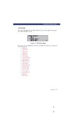
Power-On Self Test Screen
When power is first applied to the module, a series of power-on self test (POST) diagnostics is
performed. During POST execution, the model number of the module, the current date and
time, the firmware revision, and the status or result of the test in progress are displayed on the
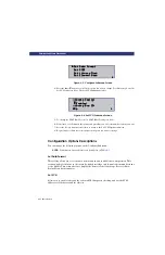
Control Panel as shown in the following figure:
Figure 3-3. POST Screen
Initialization Screens
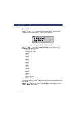
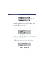
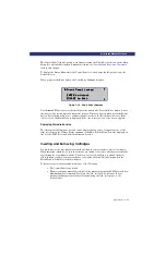
After the POST is completed, the library robotics system begins its initialization and displays a
screen similar to the following:
Firmware Version XX.XX
Firmware Version XX.XX
Firmware Version XX.XX
Firmware Version XX.XX
Checking Hardware
Checking Hardware
Checking Hardware
Checking Hardware
u
u
u
u
Summary of Contents for LXLS10
Page 1: ......
Page 4: ...xii u Preface PREFACE...
Page 8: ...iv TABLE OF CONTENTS CONT D...
Page 10: ...x LIST OF TABLES CONT D...
Page 18: ...1 6 u Introduction TAPE CARTRIDGE MAGAZINE...
Page 86: ...A 4 u Specifications SPECIFICATIONS Declaration of Conformity...
Page 90: ...Index 2 INDEX...

